+86 15340683922
 +86 15340683922
الوصف
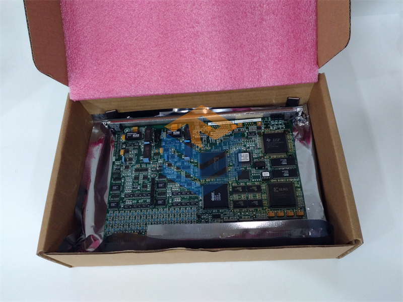
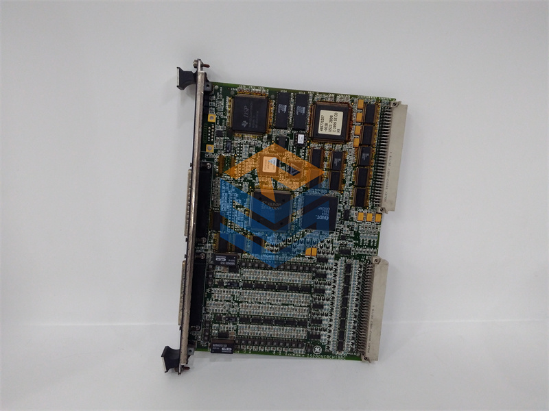
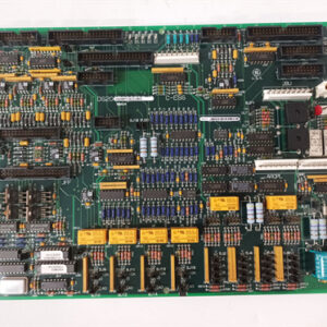
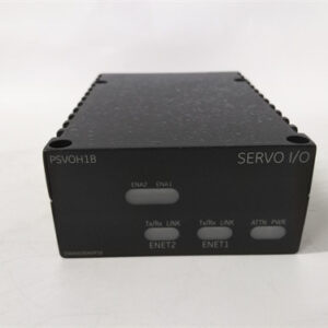
The GE DS200DMCBG1ABA is a variant of the DOS Distributed Underlying Processor (DUP) board, designed for use in the GE Mark V control system, which is commonly utilized in gas and steam turbine applications. This board plays a crucial role in managing control operations and processing data essential for the reliable operation of turbine systems. Below is an overview of its features, specifications, installation and maintenance requirements, and troubleshooting tips.
Key Features:
- Distributed Processing:
- The DS200DMCBG1ABA functions as a distributed processor, allowing it to handle input/output data efficiently in real-time.
- Input/Output Capabilities:
- This board supports multiple digital and analog I/O channels, enabling it to connect with a variety of sensors, actuators, and field devices integral to the control system’s functionality.
- Real-Time Data Management:
- Designed to meet the high-speed processing demands of turbine control applications, ensuring immediate responses to changing operational conditions.
- Modular Construction:
- The modular design simplifies installation, maintenance, and upgrades, allowing for quick replacements with minimal disruption to the control system.
- Diagnostic Features:
- Incorporated diagnostic tools, such as LED indicators, provide insights into the board’s operational status and help identify any faults that may arise.
Specifications:
- Power Requirements:
- The board operates within specific voltage and current ranges. Always refer to the manufacturer’s documentation for detailed power specifications to ensure correct installation.
- Operating Temperature Range:
- It is designed to function reliably within specified temperature limits, suitable for industrial applications.
- Physical Connections:
- The board includes a variety of connectors for integration with other components in the control system, which should be wired according to the provided schematics.
Installation and Maintenance:
- Installation:
- Follow GE’s installation guidelines meticulously to mount the board securely and connect it properly to other system components.
- Maintenance:
- Conduct regular inspections and functionality tests. Monitor LED indicators for status updates and potential faults. Ensure all connections are secure and free from damage.
- Firmware Updates:
- It is essential to keep the firmware updated. Check GE resources for the latest versions and follow prescribed procedures for installation and upgrades.
Troubleshooting Tips:
- LED Status Indicators:
- Use the onboard LEDs to check the board’s health. Abnormal LED behavior can provide immediate insight into operational issues.
- Connection Integrity:
- Regularly verify the integrity of all wiring and connectors. Loose or damaged connections often lead to performance issues.
- Diagnostic Software:
- Utilize GE’s diagnostic tools or software to perform detailed assessments of the board, helping to identify error codes or operational discrepancies.
- Consult Documentation:
- Always refer to the specific GE documentation for the DS200DMCBG1ABA for comprehensive troubleshooting procedures, wiring diagrams, and detailed operational guidance.
Documentation:
For detailed information regarding installation instructions, wiring diagrams, operational guidelines, and technical specifications for the DS200DMCBG1ABA DOS DUP Processor Board, refer to the official GE documentation and manuals.
If you have any more specific questions or need additional details regarding the DS200DMCBG1ABA board, please feel free to ask!