
 +86 15340683922
 +86 15340683922
الوصف
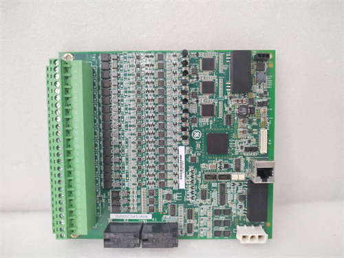
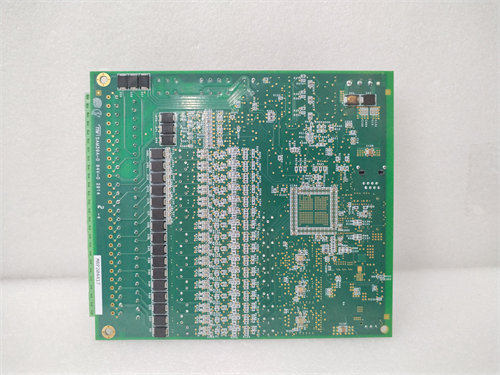
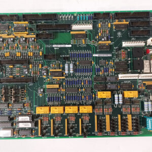
The GE DS200SDCIG1AHB is a crucial DC Power Supply and Instrumentation Board (SDCI) designed for the GE Mark V Speedtronic Turbine Control System and DC2000 Drive Series.1
Unlike the G2 boards (which we discussed earlier), the “G1” in the part number is the defining feature, indicating that this board includes an internal motor field power supply and is typically intended for use with lower-current DC motors or specific applications where field excitation requirements are limited.
Core Functions and Distinguishing Features
The DS200SDCIG1AHB performs the same two primary roles as all SDCI boards—power regulation and signal interface—but adds the internal field control functionality.
1. Integrated Field Excitation (The G1 Difference)
The primary function that sets the G1 series apart from the G2 series is the capability to directly control the DC motor’s field current using an integrated circuit on the board itself.
- Field Current Range: This internal supply is usually limited to low field currents (typically up to $10 \text{ A}$ or less), making it suitable for smaller DC motors or applications that do not require high field current regulation.
- Contactor Control: It manages the sequencing and control of the MD (Motor Field) Contactor through its circuitry.
2. Power Supply and Regulation
The board is responsible for generating all the stable, regulated voltages necessary for the sensitive digital control cards (like the SDCC) in the drive system:
- Logic Power: Provides clean DC voltages, including $+5 \text{ VDC}$ (logic), $\pm 15 \text{ VDC}$ (analog circuits), and $\pm 24 \text{ VDC}$ (drivers).
- AC Power: Supplies regulated $115 \text{ VAC}$ for internal relays and system components.
3. Instrumentation and Measurement Interface
The board acts as the central data hub for the drive, processing and isolating critical high-power signals for the main controller:
- SCR Gating Drivers: Includes the necessary circuits to generate the firing pulses for the main Armature Silicon Controlled Rectifiers (SCRs) to control motor torque and speed.
- Signal Feedback: Conditions and isolates high-level analog signals (from shunts/transducers) representing Armature Voltage, Armature Current, and Field Current, converting them into noise-immune frequency signals (using VCOs) for the digital control card.
- AC Line Monitoring: Monitors AC input signals via Current Transformers (CTs) for drive protection and diagnostics.
4. Protection and Configuration
The board includes various features to aid in system integrity and maintenance:
- Fuses and LED Indicators: Like the G2 boards, the DS200SDCIG1AHB is populated with fuses to protect power circuits. These fuses are paired with LED indicators that light up immediately upon fuse failure, simplifying troubleshooting.
- Configurable Jumpers and Switches: Includes jumpers and DIP switches (like SW1) to select options such as CT burden resistance, contactor dropout time, and control source, allowing customization to match the specific drive application.2
Part Number Breakdown (DS200SDCIG1AHB)
| Segment | Code | Meaning |
| DS200 | DS200 | GE’s Mark V DS200 Series (Circuit board assembly) |
| SDCI | SDCI | SC/DC Instrumentation (DC Power Supply and Instrumentation Board) |
| G1 | G1 | Group 1: Functional code indicating the board includes an Internal Field Excitation Circuit (for low-current field control). |
| A | A | Functional Revision 1 |
| H | H | Functional Revision 2 (indicates a specific, minor functional circuit update) |
| B | B | Artwork Revision (indicates a change in the physical PCB layout) |
Application Contrast (G1 vs. G2)
The choice between a G1 board (like SDCIG1AHB) and a G2 board (like SDCIG2AHB) is solely determined by the DC motor’s field current requirement:
| Feature | G1 (DS200SDCIG1AHB) | G2 (DS200SDCIG2AHB) |
| Field Excitation | Internal (Circuit on this board) | External (Uses a separate unit, e.g., EX2000) |
| Field Current | Low (typically $\le 10 \text{ A}$) | High (Requires high-power external supply) |
| Motor Suitability | Small to Medium DC Motors | Large, Heavy-Duty DC Motors |
In short, the DS200SDCIG1AHB is a foundational component in the GE Mark V/DC2000 line, providing regulated power, accurate motor signal measurement, and integrated control of low-current motor field excitation.