+86 15340683922
 +86 15340683922
الوصف
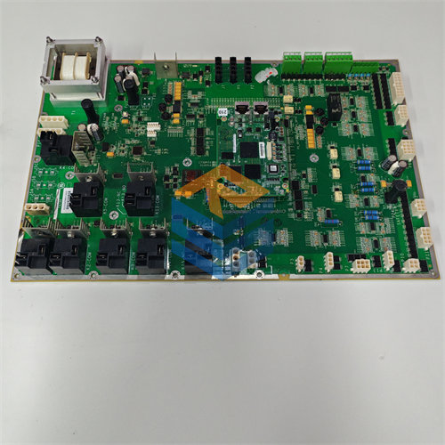
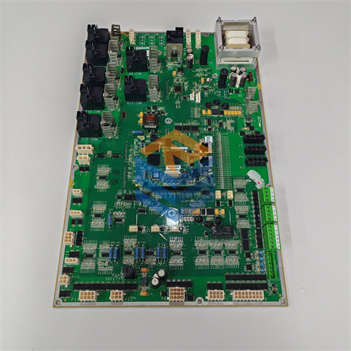
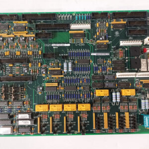
The GE DS200SPCBG1AAA Multi-Bridge Signal Processing Card is an electronic circuit board used primarily in GE’s Mark V Speedtronic Turbine Control System and associated high-performance industrial drive control applications.1
Its main function is to serve as a critical interface for signal conditioning and high-speed communication within a multi-bridge drive system.2
Key Functions and Purpose
The DS200SPCBG1AAA card manages the vital data flow necessary for synchronized, closed-loop control of a multi-bridge power converter (like a large industrial drive or excitation system).
- Encoder and Speed Feedback Processing:
- It contains two encoder follower circuits that process feedback signals from motor encoders or digital tachometers.3
- It converts these differential signals (typically 4$5\text{ V}$ or 5$15\text{ V}$) into digital up/down and marker pulse signals, which are then sent to the main Drive Control Board for speed and position calculation.6
- It contains two encoder follower circuits that process feedback signals from motor encoders or digital tachometers.3
- Analog Process Control Conditioning:
- It has two analog process control interface circuits that receive industrial control signals (e.g., 7$1-5\text{ mA}$, 8$4-20\text{ mA}$, 9$10-50\text{ mA}$, or 10$2-30\text{ V}$).11
- These circuits condition and convert the signals into a standard voltage range (like 12$\pm 5\text{ V}$ or 13$\pm 15\text{ V}$) for use by the primary control processor.14
- It has two analog process control interface circuits that receive industrial control signals (e.g., 7$1-5\text{ mA}$, 8$4-20\text{ mA}$, 9$10-50\text{ mA}$, or 10$2-30\text{ V}$).11
- High-Speed Fiber Optic Communication:
- The board provides fiber-optic transmit and receive capabilities to ensure fast, noise-immune communication.15
- This includes bridge-to-bridge communications for coordinating the multiple power bridges in the drive and master-to-master systems for control hierarchy.16
- It also transmits and receives the necessary synchronization signals to time the firing of the power semiconductor devices in the drive.17
- The board provides fiber-optic transmit and receive capabilities to ensure fast, noise-immune communication.15
System Integration
The DS200SPCBG1AAA acts as an intermediary, establishing interfaces between the following components:
- Drive Control Board (SDCC/DSPC): The SPCB connects to the main control board via a ribbon cable, delivering the conditioned encoder and analog signals.18
- Multi-Bridge Hub Communications Board (MBI-IA): It interfaces with this board to manage the synchronous communication across the various power bridges.
The card includes several adjustable hardware components for setup and fine-tuning, such as jumpers, a DIP switch (SW1) for configuring encoder inputs, and six potentiometers (P1–P6), which are used to adjust settings like zero, gain, and analog channel response time.19