+86 15340683922
 +86 15340683922
الوصف
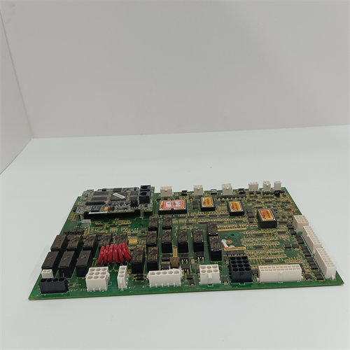
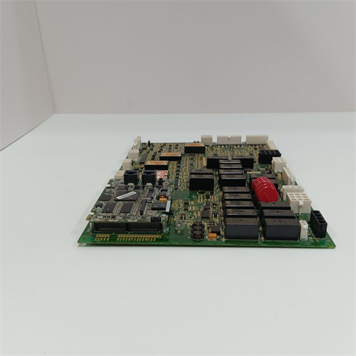
The GE DS200TBQCG1AAA Analog Input Milliamp I/O Termination Module is a critical printed circuit board (PCB) within the General Electric Mark V Speedtronic Turbine Control System.1 Its function is to provide the physical interface, or termination point, for all field wiring associated with analog current signals and position sensors, routing them to the main control electronics.2
Primary Function and Role
The board is commonly referred to by its functional acronym, TBQC (Termination Board, Quartz Crystal Reference).3
- Signal Termination: It serves as the connection point for field devices, terminating the wiring for analog I/O signals.4 This includes 4-20 mA current inputs (for monitoring pressure, flow, temperature, etc.) and Linear/Rotary Variable Differential Transformer (LVDT/R) position inputs (for valve and actuator feedback).5
- System Interface: The TBQC board is a necessary intermediary that connects these field signals to the main control processor board, specifically the TCQA (Turbine Control, Qualification, and Acquisition) board in its respective core.6
- I/O Management: It handles both inputs (4-20 mA, LVDT/R) and outputs (mA output signals, typically in the 20-200 mA range) for the turbine control system.7
- Location: It is strategically placed at position 9 within the R1, R2, and R3 control cores of the Mark V panel.8
Technical Specifications and Features
| Feature | Detail |
| Series | GE Mark V (DS200 Series) |
| Part Number Revision | The “AAA” in the part number (DS200TBQCG1AAA) indicates multiple functional and artwork revisions from the original DS200TBQCG1 board. |
| Terminal Blocks | Features two terminal blocks (TB1 and TB2), with 83 terminals each, allowing for a maximum of 166 signal wire connections. |
| Connectors | Includes multiple connectors (three 40-pin and three 34-pin) for communication with the TCQA board. The key connections are: |
| – JBR: Writes 4-20 mA input signals to the TCQA board and reads mA output signals from it. | |
| – JFR: Transmits LVDT/R position input signals to the TCQA board. | |
| – JBS/T, JFS/T, and TEST: These connections are typically unused in standard operation. | |
| Jumpers | Contains up to 15 jumpers (labeled BJ1 through BJ17) that allow for configuration, such as connecting milliamp inputs to DCOM (Digital Common) and selecting the maximum mA output current (e.g., 20 mA or 200 mA). |
| Coating | Features a normal PCB coating for protection against environmental factors. |
When replacing this board, it’s crucial to correctly match the jumper settings from the defective board to the replacement to maintain the system’s operational configuration.9