+86 15340683922
 +86 15340683922
الوصف
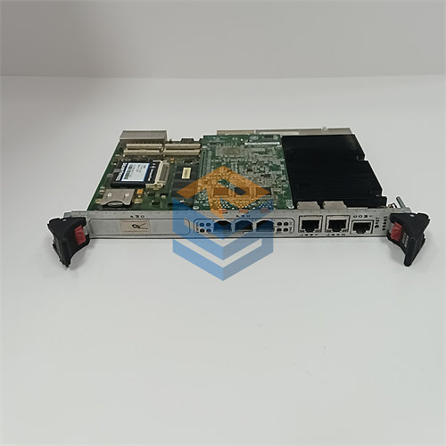
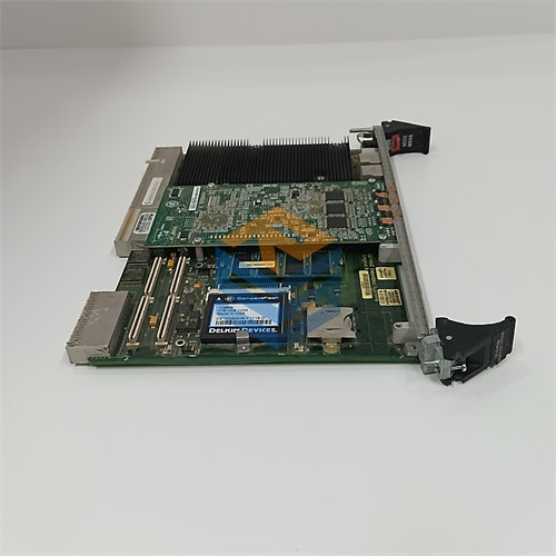
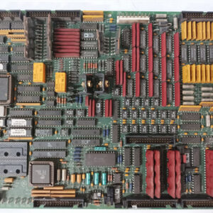
The GE DS200TBQCG1ABB Analog Input Milliamp I/O Termination Module is an essential printed circuit board (PCB) used in the General Electric Mark V Speedtronic Turbine Control System.1
Its primary function is to serve as the physical interface, or termination point, for field wiring carrying analog current and position signals, connecting them to the main control electronics.2
Key Functions and Features
- Signal Termination and Interfacing: The board, often referred to by its functional acronym TBQC (Termination Board, Quartz Crystal Reference), provides a secure, high-density connection point for analog field wiring.3 It physically routes signals from the turbine and associated machinery to the main control card.4
- Analog I/O Handling: It is designed to handle multiple types of analog signals:5
- Inputs: 4-20 mA current signals (for process variables like flow, pressure, and temperature) and LVDT/R position inputs (for valve and actuator feedback).6
- Outputs: Milliamp output signals (typically 20 mA or 200 mA, selectable via jumpers) used to drive remote indicators or auxiliary equipment.7
- Inputs: 4-20 mA current signals (for process variables like flow, pressure, and temperature) and LVDT/R position inputs (for valve and actuator feedback).6
- Connection to Main Processor: The TBQC board connects to the main control board, usually the TCQA (Turbine Control, Qualification, and Acquisition) board, located in its respective core (R1, R2, or R3) of the Mark V panel.8
- JBR Connector: Manages both the 4-20 mA input signals and the mA output signals to/from the TCQA board.9
- JFR Connector: Transmits the LVDT/R position input signals to the TCQA board.10
- JBR Connector: Manages both the 4-20 mA input signals and the mA output signals to/from the TCQA board.9
Hardware Specifications
| Component/Feature | Detail |
| Series | GE Mark V (DS200 Series) Turbine Control System |
| Functional Acronym | TBQC (Termination Board, Quartz Crystal Reference) |
| Location in Cabinet | Typically located at position 9 within the R1, R2, and R3 control cores. |
| Terminal Blocks | Features 2 terminal blocks (TB1 and TB2), each with 83 terminals, providing up to 166 connection points for signal wires. |
| Connectors | Includes multiple connectors, such as three 40-pin and three 34-pin connectors for communication with the main control board. |
| Jumpers | Contains up to 17 jumpers (BJ1-BJ17) used for configuration, such as: |
| – Connecting milliamp inputs to DCOM (Digital Common). | |
| – Selecting the maximum current output range (20 mA or 200 mA) for the two milliamp output signals. | |
| Revision | The “ABB” suffix in the part number (DS200TBQCG1ABB) indicates it is a later revision of the original base board (DS200TBQCG1), incorporating multiple functional and artwork updates. |
The configuration of the jumpers is essential for correct operation; if replacing the board, the jumper positions on the new board must be set to match those on the board being replaced.