+86 15340683922
 +86 15340683922
الوصف
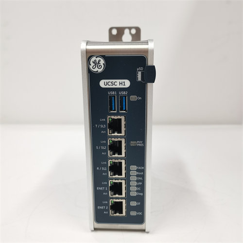
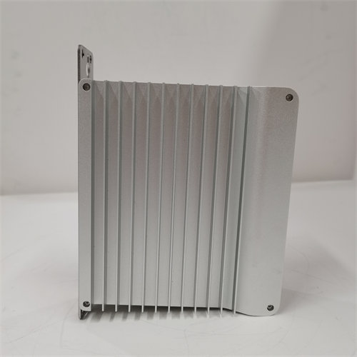
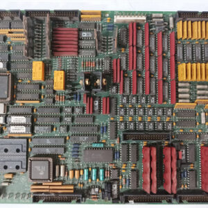
The GE DS200TBSAG1A is a Serial Communication Termination Module designed specifically for the LM Transducer interface in the GE Speedtronic Mark V Gas Turbine Control System.1
This board is specialized for Mark V applications used with aeroderivative gas turbines (like the GE 2$\text{LM6000}$), where it plays a critical dual role.3
⚙️ Primary Functions
The board’s common name, “LM Transducer Board,” reflects its application, while its official functional description points to its technical role.4
1. Serial Communication Termination (TBSA)
- Role: The board’s primary electrical function is to serve as a Serial Communication Termination Module (TBSA).5
- Purpose: It ensures signal integrity and prevents reflections on the serial communication lines, which is crucial for reliable high-speed data transfer.
- Application: It manages the serial links for devices like the FMVED (Fuel Manifold Valve Electronic Driver) motor controllers.6 These controllers regulate the precise position of fuel metering valves, making reliable communication essential for turbine fuel control.
2. Transducer Interface for LM Turbines
- Role: It functions as a specialized LM Transducer Terminal Board.7
- Purpose: This indicates it is responsible for conditioning or interfacing signals related to transducers (devices that convert a physical quantity into an electrical signal) that are unique to the 8$\text{LM}$ (aeroderivative) series of gas turbines, such as the 9$\text{LM6000}$.10
- Interface: The board’s circuitry handles the conversion of energy from the input signals coming from the turbine into the output signals needed by the Mark V’s core processor boards for regulation and monitoring.11
🎯 Technical Details
| Specification | Detail |
| Manufacturer | General Electric (GE) |
| Series | Speedtronic Mark V |
| Part Number | DS200TBSAG1A (The ‘A’ denotes a functional revision) |
| Functional Description | Serial Communication Termination Module |
| Functional Abbreviation | TBSA |
| Typical Location | Installed in one of the I/O cores, such as location 8 of the $\text{R2}$ core, in the Mark V panel. |
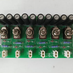
| Configuration | Includes manually-moveable jumpers (e.g., $\text{JP1}$ to $\text{JP16}$) to select communication circuits and transmission/reception options. |
This board is a key component for the control of GE’s $\text{LM}$ series turbines using the older Mark V system.