+86 15340683922
 +86 15340683922
الوصف
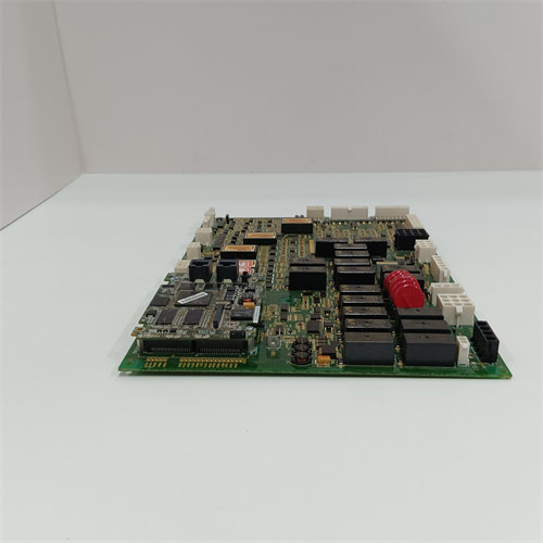
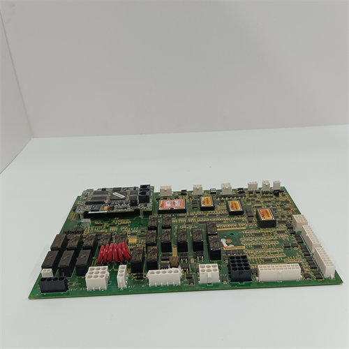
The GE DS200TCCAG1A is a Common Analog I/O Board (TCCA) manufactured by General Electric for the Speedtronic Mark V Gas/Steam Turbine Control System.
Its primary function is to serve as the central processing unit for a large group of critical analog field signals within one of the control system’s cores. It scales, conditions, and calculates these signals before passing the data to the main I/O Engine and, ultimately, to the core bus ($\text{COREBUS}$).
⚙️ Key Functions and Signal Types
The $\text{DS200TCCAG1A}$ board is typically housed in the R5 core (location $\text{R5}$ core location $\text{2}$) and interfaces with several terminal boards, including the $\text{TBQA}$ (Thermocouple), $\text{TBCA}$ (RTD), and $\text{CTBA}$ (Current/Voltage).
1. Analog Signal Conditioning
The TCCA board performs crucial tasks to prepare raw field signals for the turbine’s digital control system:
- Thermocouple Inputs: It reads thermocouple inputs from the $\text{TBQA}$ board. Importantly, it uses the cold junction signals from the $\text{TBQA}$‘s circuitry to compute the necessary cold junction compensation ($\text{CJC}$), allowing it to determine the accurate temperature.
- RTD Inputs: It provides a constant current source for Resistance Temperature Detectors ($\text{RTD}$s) and then measures, calibrates, and scales the resulting voltage signal, which corresponds to the temperature reading. These signals come from the $\text{TBCA}$ board.
- Milliamp Inputs/Outputs ($\text{4-20 mA}$):
- Inputs: It measures the voltage drop across a burden resistor created by $\text{4-20 mA}$ current signals from transducers, and then writes the scaled value to the $\text{I/O}$ Engine.
- Outputs: It drives $\text{4-20 mA}$ output signals (via the $\text{JAA}$ connector) to external remote instruments for monitoring.
2. Shaft Monitoring
The board is responsible for reading and managing the signals from the turbine’s shaft monitoring system, specifically shaft voltage and current, which are read via the $\text{JBB}$ connector.
3. Data Transfer
Once the signals are conditioned and scaled, the TCCA uses the 3PL connector as a data bus to communicate the values to the STCA board and the I/O Engine for use by the Mark V’s controllers.
🔌 Major Connectors
The board is a complex component with multiple connectors dedicated to interfacing with its respective terminal boards and the control bus:
| Connector | Description | Signal Type |
| 3PL | Data Bus | Communication channel to the $\text{STCA}$ (I/O Engine) and COREBUS. |
| 2PL | Power | Receives power distribution from the TCPS power supply board. |
| JAR/S/T | Thermocouple $\text{I/O}$ | Thermocouple and Cold Junction signals from the $\text{TBQA}$ board. |
| JCC & JDD | RTD Inputs | $\text{RTD}$ input signals from the $\text{TBCA}$ terminal board. |
| JBB | Analog $\text{I/O}$ & Shaft | $\text{4-20 mA}$ input signals, plus shaft voltage and current from the $\text{CTBA}$ board. |
| JAA | Analog Outputs | $\text{4-20 mA}$ output signals to the $\text{CTBA}$ terminal board. |