
 +86 15340683922
 +86 15340683922
الوصف
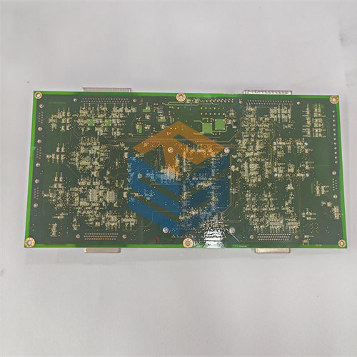
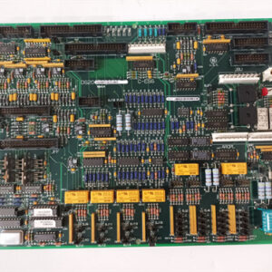
The GE DS200TCCAG1B is a Common Analog I/O Board (TCCA) that functions as a core data processor for analog signals within the GE Speedtronic Mark V Turbine Control System.1
The “B” in the part number indicates a functional revision to the original 2$\text{DS200TCCAG1A}$ board, generally meaning it has minor enhancements or fixes while maintaining the same overall functional role.3
🔬 Core Functionality
The $\text{DS200TCCAG1B}$ is a sophisticated microprocessor-based board responsible for scaling, conditioning, and digitizing a wide range of analog field data crucial for turbine operation and protection.
The board is typically located in the R5 core of the Mark V panel.4
1. Signal Processing and Conditioning
The TCCA board receives and processes critical sensor inputs from various terminal boards (like 5$\text{TBQA}$, 6$\text{TBCA}$, and 7$\text{CTBA}$), including:8
- Thermocouple Inputs: Reads raw thermocouple data, and uses the cold junction reference provided by the terminal boards to calculate the compensated, actual temperature value.9
- RTD Inputs (Resistance Temperature Detectors): Provides excitation current to the 10$\text{RTDs}$ and then measures, calibrates, and scales the resulting voltage signal to determine the temperature.11
- $4-20\text{ mA}$ Current Loops: Reads 12$\text{4-20 mA}$ input signals from remote transmitters (transducers) and drives 13$\text{4-20 mA}$ output signals to remote monitoring instruments.14
- Shaft Monitoring: Handles the processing of sensor signals related to turbine shaft voltage and shaft current.15
2. Data Transfer and Architecture
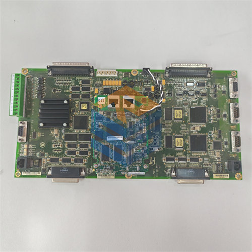
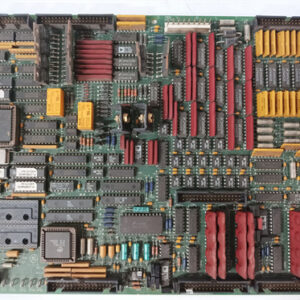
- Microprocessor: The board contains an 80196 microprocessor and multiple PROM modules (Programmable Read-Only Memory) for firmware and configuration instructions.16
- Data Bus: Conditioned data is sent from the TCCA board to the main 17$\text{I/O}$ Engine (18$\text{STCA}$ board) via the 3PL connector, which acts as a data bus to the rest of the control system.19
🧩 Hardware & Configuration
The board’s physical assembly and configuration allow it to interface and be configured specifically for the application:
| Component | Purpose |
| 3PL Connector | Main data path to the $\text{STCA}$ board (I/O Engine). |
| JCC & JDD Connectors | $\text{50-pin}$ connectors primarily used to receive RTD signals from the $\text{TBCA}$ terminal board. |
| Jumpers ($\text{J1, JP2, JP3}$) | Configurable hardware jumpers (typically three) are used to set board functions, such as enabling/disabling the $\text{RS232}$ serial port for testing. Jumper settings must be matched when replacing the board to maintain system configuration. |
| LED | A single $\text{LED}$ is provided for status indication. |
The DS200TCCAG1B is essentially the newer version of the 20$\text{TCCA}$ board, ensuring continued analog signal reliability in the 21$\text{Mark V}$ system.22