+86 15340683922
 +86 15340683922
الوصف
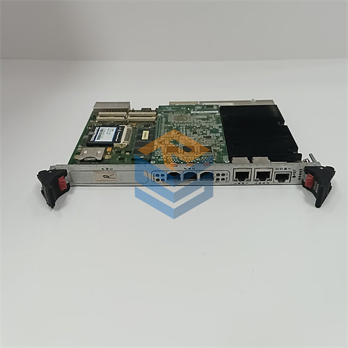
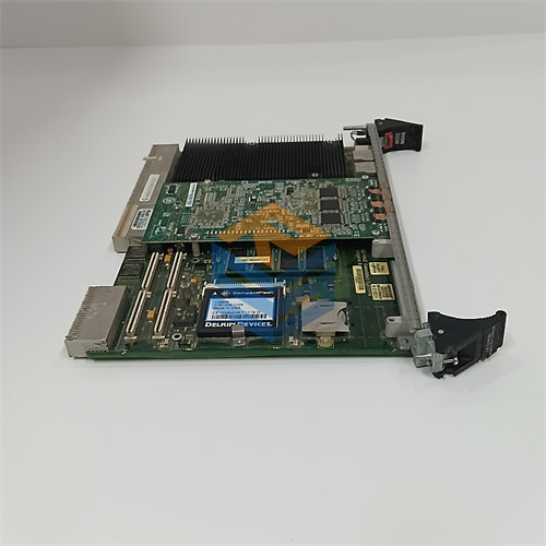
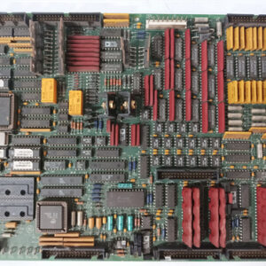
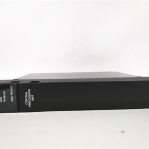
The GE $\text{DS200TCCAG1BAA}$ I/O TC2000 Analog Board is a vital printed circuit board (PCB) within the GE Speedtronic Mark V Turbine Control System, specifically designed as the TC2000 Common Analog I/O Module ($\text{TCCA}$).
This board’s main role is to process, condition, and digitize a wide array of analog signals from field devices, making that data available to the main controllers of the turbine control system.
⚙️ Key Functions and Signal Processing
The $\text{DS200TCCAG1BAA}$ acts as an intermediate processor for all essential analog inputs and outputs, ensuring signal integrity and accuracy. It is typically mounted in the R5 core location of the Mark V panel.
- Signal Conditioning: It scales and conditions analog signals received from various terminal boards (like $\text{TBQA}$, $\text{TBCA}$, and $\text{CTBA}$).
- Thermocouple Inputs: It receives thermocouple readings and uses the cold junction reference to calculate the true, compensated temperature value.
- RTD Inputs (Resistance Temperature Detectors): It supplies the necessary excitation current to the $\text{RTDs}$ and measures the resulting voltage to determine the precise temperature.
- $\text{4-20 mA}$ Current Loops: It provides circuitry for reading $\text{4-20 mA}$ input signals from process transducers and for driving $\text{4-20 mA}$ output signals to remote instrumentation and monitoring systems.
- Shaft Monitoring: It processes signals related to turbine shaft voltage and current.
The processed analog data is then transmitted to the main I/O Engine ($\text{STCA}$ board) via the 3PL connector for use by the turbine’s control and protection logic.
💻 Hardware and Revisions
The board is a microprocessor-based system with specific hardware features:
- Microprocessor: Features an 80196 microprocessor to manage data processing and communications.
- Memory: Includes multiple PROM modules (Programmable Read-Only Memory) that store the essential firmware, operating instructions, and configuration code for the board. These modules are often transferred from the old board to a replacement to ensure identical performance.
- Connectors:
- 3PL: Main data bus connector for communication with the $\text{STCA}$ board.
- JCC and JDD: Two $\text{50-pin}$ connectors for analog signal inputs, often specifically handling $\text{RTD}$ signals from the $\text{TBCA}$ terminal board.
- Jumpers ($\text{J1}$, $\text{JP2}$, $\text{JP3}$): Typically three configurable hardware jumpers are used to set board functions (e.g., enabling/disabling the $\text{RS232}$ port or factory test modes).
Understanding the Part Number
The full part number, $\text{DS200TCCAG1BAA}$, indicates multiple revisions to the original design:
| Segment | Meaning |
| $\text{DS200}$ | Product Family (Mark V $\text{DS200}$ Series) |
| $\text{TCCA}$ | Functional Acronym (TC2000 Common Analog) |
| $\text{G1}$ | Group 1 (typically related to assembly or coating) |
| $\text{B}$ | 1st Functional Revision (Revision B) |
| $\text{AA}$ | 2nd Functional Revision and Artwork Revision (Revision A for both) |
The multiple revisions ($\text{BAA}$) signify that this board is an improved and refined version of the base $\text{DS200TCCAG1}$ design, often incorporating bug fixes or hardware upgrades over earlier iterations.