+86 15340683922
 +86 15340683922
الوصف
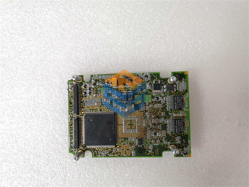
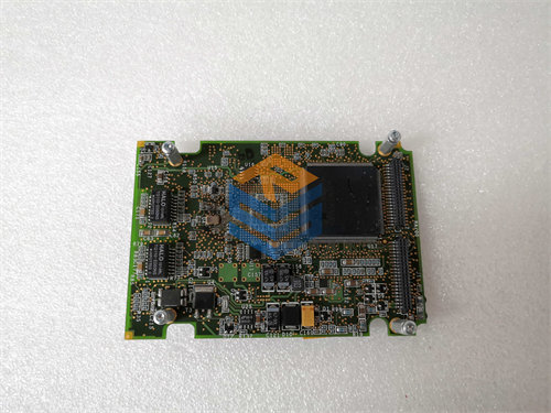
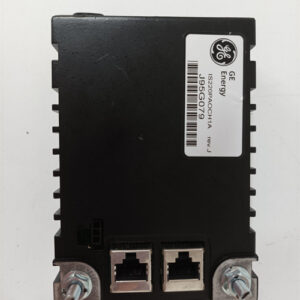
The GE DS200TCCAG2A is a Common Analog I/O Board ($\text{TCCA}$), a fundamental component of the GE Speedtronic Mark V Turbine Control System.
This board is an analog data processor that scales and conditions raw analog signals from the field devices before sending the data to the main digital controllers. The “G2” in the part number indicates a different hardware group or design compared to the $\text{G1}$ versions ($\text{DS200TCCAG1A/B}$), but it serves the same critical function within the turbine control architecture.
⚡ Key Functions and Role in Mark V
The $\text{DS200TCCAG2A}$ is typically installed in the R5 core VME backplane slot of the turbine control panel. Its primary responsibilities include:
- Signal Acquisition and Conditioning: It receives a variety of raw analog signals from external terminal boards ($\text{CTBA}$, $\text{TBQA}$, $\text{TBCA}$) and processes them to ensure accuracy and stability.
- Temperature Measurement:
- Thermocouple Inputs: Reads inputs and uses cold junction circuitry to calculate the actual, compensated temperature.
- RTD Inputs (Resistance Temperature Detectors): Supplies excitation current to the $\text{RTDs}$ and measures the resulting voltage change to determine temperature.
- Process Signal I/O: Provides circuitry for handling $\text{4-20 mA}$ analog input signals (from pressure, flow, or vibration transmitters) and for driving $\text{4-20 mA}$ analog output signals (to local instrumentation or final control elements).
- Shaft Monitoring: It processes signals for turbine shaft voltage and shaft current.
- Data Communication: The processed, digitized, and conditioned signals are then transferred to the main $\text{STCA}$ (I/O Engine) board via the 3PL connector (the Data Bus) for use in the turbine control and protection algorithms.
💻 Hardware and Connectivity
The $\text{DS200TCCAG2A}$ includes the necessary processing and interface hardware:
| Feature | Details |
| Processor | Typically an 80196 microprocessor for control and data management. |
| Connectors | Includes several multi-pin connectors for interface to terminal boards and the backplane, such as 3PL (Data Bus), 2PL (Power), JAA ($\text{4-20 mA}$ outputs), JBB ($\text{4-20 mA}$ inputs / Shaft monitoring), and JCC/JDD ($\text{RTD}$ inputs). |
| Jumpers | Three hardware jumpers (J1, JP2, JP3) are present for configuring the board (e.g., enabling the $\text{RS232}$ serial port or for factory tests). Jumper settings must be carefully matched when replacing a board. |
| Additional Feature | Some revisions, including the G2, may feature on-board RAM to enhance data processing and storage capabilities, crucial for real-time control tasks. |
The key difference implied by the “G2” in the part number (compared to “G1”) is an internal hardware distinction or revision, often related to the board’s construction, such as compatibility with a different generation of the VME bus or a different hardware layout, though the fundamental function ($\text{TCCA}$) remains the same.