+86 15340683922
 +86 15340683922
الوصف
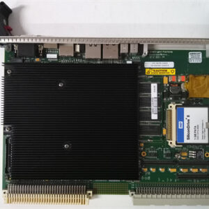
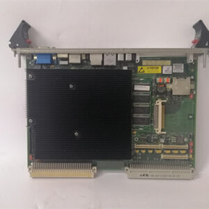
The GE $\text{DS200TCCAG2B}$ is a Common Analog I/O Board (functional acronym $\text{TCCA}$) used in the GE Speedtronic Mark V Turbine Control System.
It serves as the critical interface board that converts raw analog signals from the turbine’s sensors into digital data for the main control processors. The primary difference between the $\text{TCCAG2B}$ and earlier revisions ($\text{G1}$ or $\text{G2A}$) is typically a minor hardware, firmware, or component update, designated by the final “$\text{B}$” revision level. It still belongs to the same hardware grouping (“$\text{G2}$“).
🛠️ Board Functionality and Signal Handling
The $\text{TCCA}$ board is generally located in the R5 core of the Mark V control panel, often mounted in a VME backplane slot. Its main function is signal acquisition, conditioning, and transmission to the I/O Engine ($\text{STCA}$ board).
| Signal Type | Function Handled by TCCA | Interface Terminal Board |
| Thermocouple Inputs | Reads and uses cold junction compensation signals to calculate the true temperature. | $\text{TBQA}$ (Thermocouple Terminal Board) |
| $\text{RTD}$ Inputs | Provides excitation current to the $\text{RTDs}$, measures the voltage, and scales the signal to determine temperature. | $\text{TBCA}$ (RTD Terminal Board) |
| $\text{4-20 mA}$ Inputs | Reads the current loop signals from process transmitters (e.g., pressure, flow) by measuring the voltage drop across a burden resistor. | $\text{CTBA}$ (I/O Terminal Board) |
| $\text{4-20 mA}$ Outputs | Drives analog current outputs to remote monitoring systems or control valves. | $\text{CTBA}$ (I/O Terminal Board) |
| Shaft Monitoring | Processes signals for shaft voltage and shaft current. | $\text{CTBA}$ (I/O Terminal Board) |
Once the signals are conditioned, they are transmitted across the core’s data bus to the main processing boards via the 3PL connector.
⚙️ Key Hardware Components
Like other $\text{TCCA}$ variants, the $\text{DS200TCCAG2B}$ is a microprocessor-based module:
- Microprocessor: Features an 80196 microprocessor to perform the complex tasks of signal scaling and communication.
- Memory: Utilizes PROM modules (Programmable Read-Only Memory) to store the board’s operational instructions and firmware. These PROMs are often swapped from the original board to a replacement to maintain consistent control logic.
- Connectors:
- 3PL: The main data bus connector that links the $\text{TCCA}$ to the $\text{STCA}$ (Simplex Trip Core Analog) and $\text{TCCB}$ boards.
- JCC / JDD: Connectors typically used for carrying $\text{RTD}$ input signals from the $\text{TBCA}$ terminal board.
- JAA / JBB: Connectors used for transferring $\text{4-20 mA}$ inputs/outputs and shaft monitoring signals to/from the $\text{CTBA}$ terminal board.
- Jumpers: Includes three configurable hardware jumpers (J1, JP2, J3) used for setting specific functions, such as enabling/disabling the $\text{RS232}$ port or test modes.