+86 15340683922
 +86 15340683922
الوصف
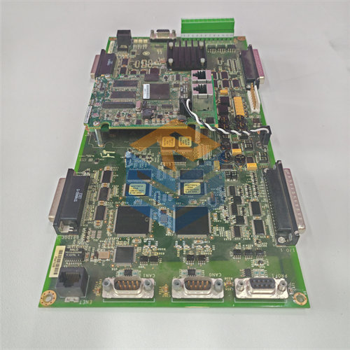
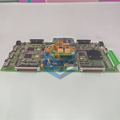
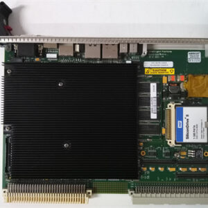
The GE DS200TCCBG1B is an Extended Analog I/O Board designed for the GE Speedtronic Mark V Gas/Steam Turbine Control System.1 Its primary role is to expand the system’s analog input/output capacity by providing crucial signal conditioning and scaling for various field devices.2
⚙️ Primary Function
The main function of the 3$\text{DS200TCCBG1B}$ (functional acronym 4$\text{TCCB}$) is to process, scale, and condition additional analog I/O signals for the Mark V controller.5 It typically works in conjunction with two main terminal boards:6
- TBCB (Terminal Board Common B):7 Signals read from this terminal board (often relating to 8$\text{RTDs}$ and current loops) are conditioned by the TCCB.9
- TCEB (Terminal Board Common E): The TCCB processes signals from this board as well.10
The board offloads some of the I/O processing from the main control processor, specifically handling:
- $\text{RTD}$ Circuits: It provides the necessary excitation current to 11$\text{RTD}$ (Resistance Temperature Detector) sensors and then measures, scales, and conditions the resulting voltage changes to determine temperature.12
- Current Loops: It provides the circuitry to process standard industrial current input signals, such as 13$\text{4-20 mA}$ and 14$\text{0-1 mA}$ signals.15
- Power Signals: It scales and conditions voltage and current signals from 16$\text{PT}$ (Potential Transformer) and 17$\text{CT}$ (Current Transformer) inputs, which are used to calculate generator 18$\text{kW}$, power factor, and 19$\text{VARs}$.20
💾 Technical Specifications and Components
The 21$\text{DS200TCCBG1B}$ is a printed circuit board (22$\text{PCB}$) with several critical components:23
| Component | Detail |
| Microprocessor | Contains one $\text{80196 CPU}$ dedicated to I/O processing. |
| Memory | Features multiple $\text{PROM}$ modules. These hold the board’s operational firmware and must be transferred to a replacement board to maintain configuration. |
| Connectors | Includes two main $\text{50-pin connectors}$ ($\text{JCC}$ and $\text{JDD}$) and several other connectors ($\text{3PL}$, $\text{JHH}$, etc.) for ribbon cable communication with other boards and the I/O engine. |
| Jumpers | Equipped with several hardware jumpers ($\text{JP1}$, $\text{JP2}$, $\text{JP3}$, etc.) that allow an installer to set or change board configuration values to match specific system requirements. |
| Indicator | Includes a single $\text{LED}$ (Light Emitting Diode), typically visible from the side, which provides a health or power status indication. |
The “24$\text{B}$” at the end of the part number (25$\text{DS200TCCBG1**B**}$) indicates that this board is the first functional revision of the 26$\text{DS200TCCBG1}$ hardware generation.27