+86 15340683922
 +86 15340683922
الوصف
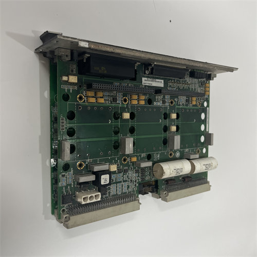
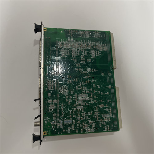
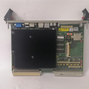
The GE DS200TCCBG1BED is an Extended Analog I/O Board designed for the General Electric Speedtronic Mark V Gas/Steam Turbine Control System. Its role is to expand the system’s analog input and output capabilities by performing essential signal conditioning, scaling, and processing for various field devices.
⚙️ Primary Function and Role
The board, often referred to by its functional acronym $\text{TCCB}$, acts as an I/O processor for additional analog signals that are critical for turbine control and monitoring.
- Signal Conditioning and Scaling: Its main job is to take raw analog signals from field devices, condition them (filter noise, isolate), and scale them into usable engineering units for the main Mark V controller.
- $\text{RTD}$ Input Control: A primary function is to interface with $\text{RTD}$ (Resistance Temperature Detector) sensors to accurately measure temperature variations in equipment like motors and generators. The board provides the excitation current, measures the resulting voltage change, and converts it to a temperature reading.
- Current and Voltage Processing: It handles standard industrial analog input signals, including $\text{4-20 mA}$ and $\text{0-1 mA}$ current loops, which measure process variables like flow, pressure, or level. It also processes scaled voltage and current signals from $\text{PT}$ (Potential Transformer) and $\text{CT}$ (Current Transformer) inputs for power system monitoring (e.g., calculating generator $\text{kW}$, power factor, and $\text{VARs}$).
🛠️ Technical Specifications
The $\text{DS200TCCBG1BED}$ is a printed circuit board ($\text{PCB}$) with a dedicated internal processor:
| Feature | Detail |
| Processor | One $\text{80196}$ Microprocessor ($\text{CPU}$) for local I/O processing. |
| Memory | Multiple $\text{PROM}$ modules (Programmable Read-Only Memory) hold the board’s firmware and configuration. When replacing the board, these modules typically need to be moved from the old board to the new one. |
| Connectors | Includes various connectors, notably two $\text{50-pin connectors}$ ($\text{JCC}$ and $\text{JDD}$), which facilitate ribbon cable connection to other boards in the system. |
| I/O Connectors | Key connectors interface with terminal boards: $\text{JHH}$ (for $\text{4-20 mA}$ inputs), $\text{JII}$ (for $\text{RTD}$ inputs), and $\text{JMP}$ (for $\text{PT/CT}$ signals from the $\text{TCEB}$ board). |
| Configuration | Features hardware jumpers ($\text{JP1}$, $\text{JP2}$, $\text{JP3}$, etc.) that are manually set to configure the board’s functionality for the specific application. |
The final part of the designation, “$\text{BED}$,” indicates the board’s functional and cosmetic revision levels, suggesting a later, highly compatible version within the $\text{Mark V}$ series.