+86 15340683922
 +86 15340683922
الوصف
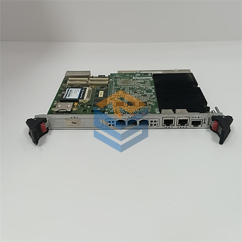
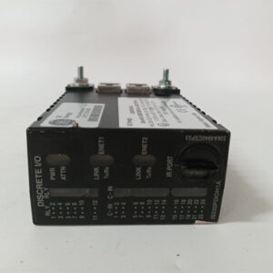
The GE $\text{DS200TCCBG3A}$ is a Common Extended Analog I/O Board for the General Electric Speedtronic $\text{Mark V}$ Gas and Steam Turbine Control System.
Its primary role is to expand, condition, and process additional analog input and output signals beyond the capacity of the main analog I/O board. It performs crucial signal processing to ensure accurate data is fed to the turbine’s control processors.
⚙️ Key Functions and Signal Processing
The $\text{DS200TCCBG3A}$ is a highly specialized circuit board responsible for handling a variety of input signals related to turbine and generator performance:
- Signal Conditioning and Scaling: The board receives raw analog signals from sensors and transducers, where it performs necessary filtering, isolation, amplification, and scaling. This ensures the signals are clean, accurate, and converted into the correct digital format for the main $\text{Mark V}$ processors.
- Sensor Input Processing: It manages inputs from:
- $\text{4-20 mA}$ and $\text{0-1 mA}$ current inputs (common for pressure, flow, and level transmitters).
- $\text{RTD}$s (Resistance Temperature Detectors) for precise temperature measurements.
- Generator and Electrical Monitoring: A significant function is the processing of signals from Potential Transformers ($\text{PT}$s) and Current Transformers ($\text{CT}$s) to monitor and calculate:
- Generator and bus voltage inputs.
- Line current inputs.
- This data is used by software transducers on the board to calculate real-time generator metrics, which are then passed to the main $\text{Mark V}$ control regulators.
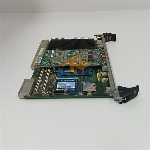
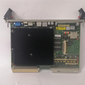
💻 Technical Architecture
The board is a microprocessor application board ($\text{TCCB}$) and contains its own dedicated components to manage its I/O tasks:
| Component | Detail |
| Microprocessor ($\text{CPU}$) | One $\text{80196}$ Microprocessor for running I/O application software and communication. |
| Revision Group | $\text{G3}$ (Group 3), indicating it is a later functional or component revision within the $\text{TCCB}$ family, designed to be backwards-compatible with previous revisions. |
| I/O Connectors | Includes two $\text{50-pin}$ connectors ($\text{JCC}$ and $\text{JDD}$) and typically five $\text{34-pin}$ connectors for interfacing with ribbon cables that connect to the terminal boards (like $\text{TBCB}$ in the $\text{R5}$ core or $\text{TCEB}$ in the $\text{P1}$ core). |
| Configuration | Features multiple jumpers ($\text{J1}$, $\text{J2}$, $\text{J3}$, $\text{J4}$, $\text{J5}$) that are used to enable specific functions, such as generator voltage and line current monitoring for a given turbine setup. |
The board plays a critical role in the $\text{Mark V}$‘s $\text{TMR}$ (Triple Modular Redundant) architecture, ensuring that the control system has robust and conditioned data to execute its control and protective functions for safe and efficient turbine operation.