
 +86 15340683922
 +86 15340683922
الوصف
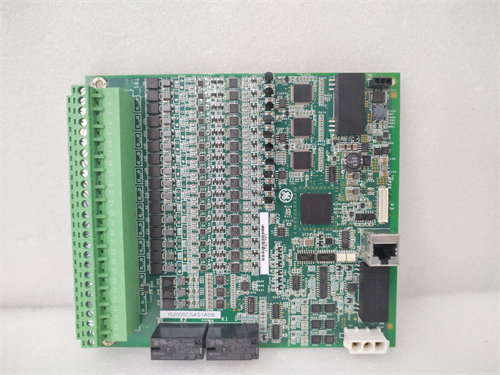
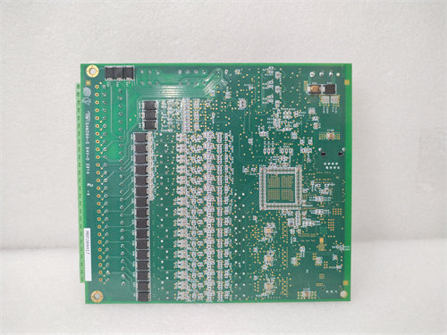
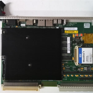
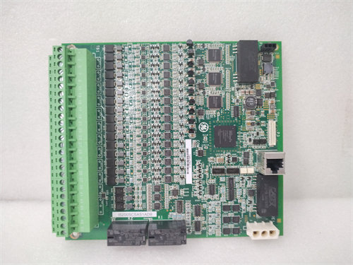
The GE $\text{DS200TCCBG3BDC}$ is a specific revision of the Common Extended Analog $\text{I/O}$ Board for the General Electric Speedtronic $\text{Mark V}$ Turbine Control System. It is often referred to as an 1$\text{I/O TC2000}$ Analog Board.2
This board is an integral component designed to handle a supplemental set of complex analog signals beyond those managed by the primary controllers, ensuring accurate monitoring and control of the gas or steam turbine and generator.
⚙️ Key Functionality
The $\text{DS200TCCBG3BDC}$ provides the crucial interface for extended signal processing, primarily focusing on conditioning, scaling, and conversion of field measurements.
Signal Types Processed
- Generator Electrical $\text{I/O}$: It processes isolated and scaled signals from Potential Transformers ($\text{PT}$s) and Current Transformers ($\text{CT}$s) to monitor and calculate:3
- Generator Voltage
- Bus Voltage
- Line Current
- Temperature and Process $\text{I/O}$: It handles various industrial signals, including:
- $\text{RTD}$ inputs (Resistance Temperature Detectors) for accurate temperature readings.
- $\text{4-20 mA}$ / $\text{0-1 mA}$ current loop inputs from pressure, flow, and level transmitters.
Technical Operation
The board is essentially a microprocessor application board featuring an 4$\text{80196}$ CPU and multiple 5$\text{PROM}$ modules to store firmware and application-specific code.6 Its operational sequence involves:
- Receiving raw analog signals from associated terminal boards (like 7$\text{TBCB}$ in the 8$\text{R5}$ core and 9$\text{TCEB}$ in the 10$\text{P1}$ core).11
- Using the onboard microprocessor and software algorithms to perform transducing, linearization, and scaling.12
- Converting the conditioned analog voltage signals into digital data using Voltage-Controlled Oscillators ($\text{VCO}$s).13
- Transmitting the final, scaled digital data to the $\text{Mark V}$‘s main control processors ($\text{R}$, $\text{S}$, $\text{T}$) via the COREBUS connector ($\text{3PL}$).
📋 Part Number Breakdown
The full part number $\text{DS200TCCBG3BDC}$ includes several revision identifiers:
- $\text{DS200}$: The product series for $\text{Mark V}$ components.
- $\text{TCCB}$: The functional acronym for the $\text{TC2000}$ Common Extended Analog $\text{I/O}$ Board.
- $\text{G3}$: Indicates the Group 3 hardware design generation.
- $\text{B}$ (First $\text{B}$): The Functional Revision.
- $\text{D}$: A subsequent functional or component revision.
- $\text{C}$: Another minor functional or artwork revision.
The multiple trailing letters (BDC) denote a specific combination of functional and artwork revisions made to the base $\text{G3}$ design. When replacing the board, it is critical to match the revision or use a newer, guaranteed backward-compatible version, and often to transfer the $\text{PROM}$ modules to ensure the correct application software is running.