
 +86 15340683922
 +86 15340683922
الوصف
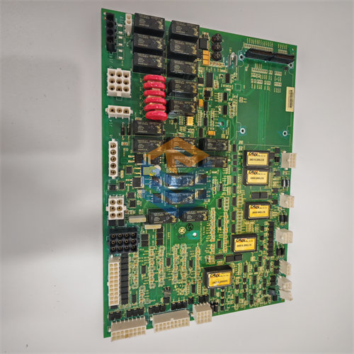
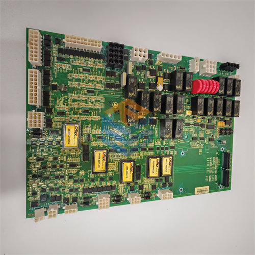
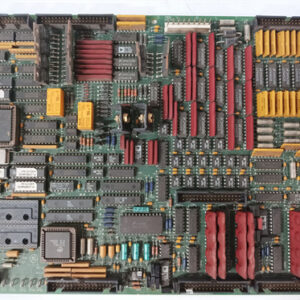
The GE 1$\text{DS200TCCBG8B}$ is a Common Extended Analog 2$\text{I/O}$ Board—also known by its acronym 3$\text{TCCB}$—that belongs to the General Electric 4$\text{Speedtronic Mark V}$ Turbine Control System series.5
It’s an essential component used to interface with and process a large set of analog signals crucial for the operation and protection of gas, steam, and wind turbines.6 The “$\text{G8}$” in the part number indicates it is a later hardware generation of the $\text{TCCB}$ design.
🛠️ Key Functionality
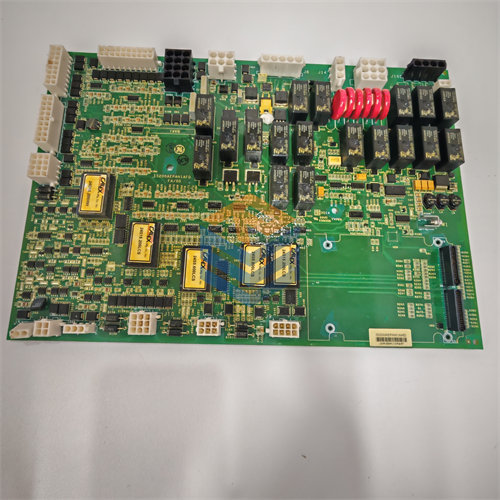
The primary role of the 7$\text{DS200TCCBG8B}$ is to condition, scale, and convert raw analog field signals into digital data that the triple-redundant 8$\text{Mark V}$ controllers (9$\text{R}$, 10$\text{S}$, 11$\text{T}$) can use for control and protection algorithms.12
🔌 Signal Processing
The board handles a variety of auxiliary analog input signals that are typically terminated on associated terminal boards (like 13$\text{TBCB}$ in the 14$\text{R5}$ core).15 These signals include:
- Generator and Bus Voltage/Current: It processes isolated and scaled signals from Potential Transformers ($\text{PT}$s) and Current Transformers ($\text{CT}$s) to calculate power system data like Megawatts, VARs, and Power Factor.16
- Process Inputs: It processes standard industrial current loops such as 17$\text{4-20 mA}$ / 18$\text{0-1 mA}$ signals from transmitters for parameters like pressure, flow, and level.19
- Temperature Inputs: It handles signals for Resistance Temperature Detectors ($\text{RTD}$s), measuring and scaling temperature for control and monitoring.20
🖥️ Technical Operation
- Microprocessor: The board features an internal microprocessor (often an 21$\text{80196}$ CPU) which executes complex software transducing algorithms to scale and condition the raw signals.22
- Data Flow: Conditioned digital data is transmitted to the main control system’s 23$\text{I/O}$ Engine via the 24$\text{3PL}$ connector on the COREBUS, where it is used by the control processors.25
- Configuration: The board includes several hardware jumpers (26$\text{J1}$ through 27$\text{J5}$) used to configure functions like generator/bus voltage monitoring and line current monitoring, particularly in 28$\text{Mark V LM}$ (Load Management) applications.29 It also features a jumper (30$\text{J14}$) to connect its 31$\text{RS232}$ serial port for diagnostics.32
⚙️ Board Specifications
| Feature | Detail |
| Control System | $\text{GE Speedtronic Mark V}$ (including $\text{LM}$ series) |
| Functional Acronym | $\text{TCCB}$ |
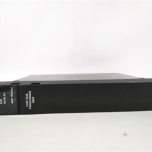
| Board Location | Typically installed in the $\text{R5}$ core of the control panel |
| Processor | $\text{80196}$ Microprocessor |
| Memory | Multiple $\text{PROM}$ or $\text{EEPROM}$ modules (for firmware/configuration) |
| Input Type | $\text{RTD}$s, $\text{4-20 mA}$ / $\text{0-1 mA}$, Scaled $\text{PT/CT}$ signals |
When replacing this board, it is standard procedure to transfer the $\text{PROM}$ or $\text{EEPROM}$ modules from the faulty board to the replacement board to ensure the new hardware runs with the correct, site-specific application code.