+86 15340683922
 +86 15340683922
الوصف
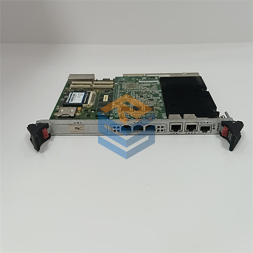
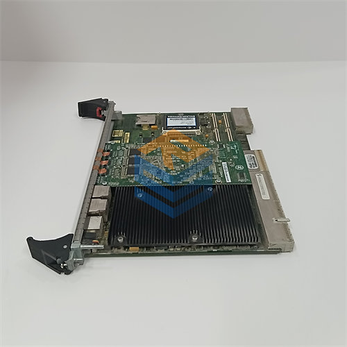
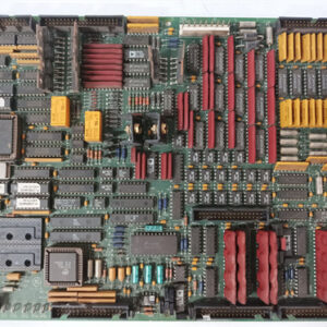
The GE $\text{DS200TCCBG8BED}$ is a highly-revised model of the Common Extended Analog $\text{I/O}$ Board ($\text{TCCB}$), designed for the General Electric $\text{Speedtronic Mark V}$ Turbine Control System, particularly the $\text{Mark V LM}$ (Load Management) series.
Its core function is to expand the system’s capacity for processing critical analog signals beyond the main control core, ensuring precise monitoring and control of gas, steam, and wind turbines.
🔬 Function and Purpose
The $\text{DS200TCCBG8BED}$ acts as an intermediate processing board for supplementary analog data. It is typically installed in the $\text{R5}$ core of the $\text{Mark V}$ panel.
- Signal Conditioning and Scaling: The board receives various raw analog input signals from dedicated terminal boards (like $\text{TBCB}$ and $\text{TCEB}$). It conditions, scales, and converts these analog signals into a digital format suitable for the main $\text{Mark V}$ processors.
- Key Signals Handled:
- $\text{RTD}$ Inputs: Temperature measurements from Resistance Temperature Detectors.
- Current Inputs: Standard industrial signals, typically $\text{4-20 mA}$ or $\text{0-1 mA}$, for various process variables (pressure, flow, level).
- Power System Inputs: Scaled signals from Potential Transformers ($\text{PT}$s) and Current Transformers ($\text{CT}$s) to monitor Generator/Bus Voltage and Line Current.
- Data Processing: It uses an onboard microprocessor to run software transducer algorithms. These calculations determine critical power system metrics like Megawatts, VARs, and Power Factor, which are then used by the turbine control regulators.
- Data Transmission: The conditioned and scaled digital data is sent to the $\text{STCA}$ board via the $\text{3PL}$ connector for use by the redundant control processors ($\text{R}$, $\text{S}$, $\text{T}$).
📑 Part Number Breakdown
The full part number indicates its series, design group, and revision history:
- $\text{DS200}$: $\text{Mark V}$ Series designation.
- $\text{TCCB}$: Functional Acronym for TC2000 Common Core Board (Common Extended Analog $\text{I/O}$ Board).
- $\text{G8}$: The Group $\text{8}$ hardware design generation.
- $\text{B}$ (First $\text{B}$): An initial functional revision.
- $\text{E}$ (Second $\text{E}$): A subsequent functional revision.
- $\text{D}$ (Third $\text{D}$): Another minor functional or artwork revision.
The trailing letters ($\text{BED}$) indicate that this board is a very mature product with several updates over the original $\text{G8}$ version, incorporating bug fixes and enhancements.
📌 Configuration
Configuration is managed through a combination of hardware and software settings:
- Hardware Jumpers: Jumpers ($\text{J1}$ through $\text{J5}$) on the board are used to physically enable and configure monitoring functions for generator and bus voltage and line current, necessary for $\text{Mark V LM}$ applications. Another jumper ($\text{J14}$) is used to link the $\text{RS232}$ serial port to the system’s $\text{DCOM}$ (Data Communication).
- Software Configuration: Specific I/O constants for $\text{RTD}$ types, current ranges, and voltage settings are entered via the $\text{I/O}$ Configuration Editor on the Human-Machine Interface ($\text{HMI}$).
- $\text{PROM}$ Modules: The board contains multiple programmable modules ($\text{EEPROM}$ or $\text{PROM}$). When replacing the board, these modules must be transferred from the original, faulty board to the replacement to ensure the correct site-specific configuration and firmware are maintained.