
 +86 15340683922
 +86 15340683922
الوصف
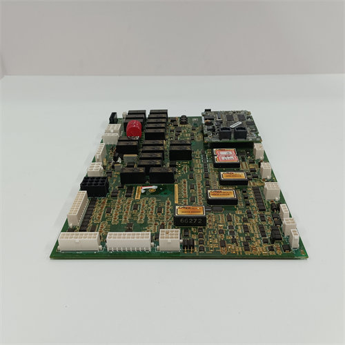
The GE Emergency Overspeed Board is a vital safety component of the General Electric Turbine Control System. Its main purpose is to provide triple-redundant, independent protection against a catastrophic turbine overspeed condition.
It is often referred to by its functional acronym, ($\text{T}$urbine $\text{C}$ontrol $\text{E}$mergency $\text{A}$uxiliary or $\text{T}$urbine $\text{C}$ontrol $\text{E}$lectronic $\text{A}$uxiliary board).
🛡️ Critical Safety Function
The board operates as part of the ‘s dedicated Protective Core ( Core), which enforces the safety trip logic independently of the main control processor.
- Overspeed Detection: The board continuously monitors the turbine’s rotational speed, receiving signals from speed sensors (typically magnetic pickups) and scaling the input.
- Emergency Trip: If the turbine speed exceeds a pre-determined, high emergency limit (typically % of rated speed), the board initiates an immediate, hard-wired emergency trip to shut down the turbine.
- Redundancy: In the system, three identical boards are typically used in the Protective Core (designated as the , , and processors). This redundancy allows for a 2-out-of-3 () voting logic at the final output stage (on the $\text{T}$urbine $\text{T}$rip $\text{G}$ate board) to ensure the trip signal is reliable and not caused by a single component failure.
- Auxiliary Functions: Besides overspeed protection, the board also handles input signals for other critical protective functions, such as flame detection and potentially high/low shaft speed limits.
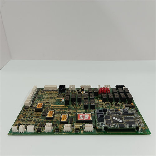
💻 Hardware and Configuration
The board is a complex processor card designed for high reliability and speed.
| Feature | Description |
| Location | Mounted in the dedicated Protective Core () of the cabinet. |
| Processor | Typically equipped with a dedicated microprocessor (e.g., an ) to execute the high-speed safety logic. |
| Configuration | Features a large number of jumpers (up to on some revisions) to program the board for its specific location (X, Y, or Z) within the core. These jumpers must be set correctly if the board is moved. |
| Connectors | Includes multiple connectors (, , , , , ) for power, speed signals, flame detection signals, and connection to the and the trip board. |
| Revisions | The full part number indicates a specific revision series: (Group 1), (Primary Functional Revision), (Secondary Functional Revision), and (Artwork Revision). |
The is one of the most important boards in the system, as its correct function directly correlates with the physical safety and protection of the turbine machinery.