
 +86 15340683922
 +86 15340683922
الوصف
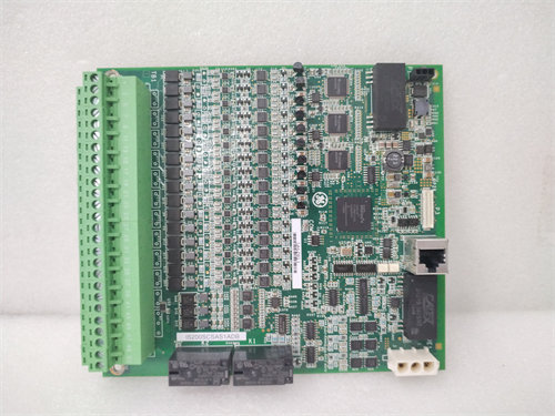
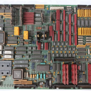
The GE DS200TCDAG1B is a Digital Input/Output ($\text{I/O}$) Card (or board), also known by its functional acronym $\text{TCDA}$, designed for use in the GE $\text{Speedtronic Mark V}$ Turbine Control System.
Its primary role is to manage and process the on/off (digital) signals required for turbine sequencing, operation, and control logic.
⚙️ Core Functionality
The $\text{TCDA}$ board acts as a digital signal interface within the $\text{Mark V}$‘s architecture, specifically handling the flow of discrete signals.
- Digital Input Processing: It receives and processes digital contact input signals from terminal boards (like $\text{DTBA}$ and $\text{DTBB}$), which represent the status of physical devices (e.g., limit switches, pressure switches, operator pushbuttons, and alarms).
- Digital Output Control: It handles the control signals for contact outputs (like relays and solenoids) by sending data to boards such as the $\text{TCRA}$ (Turbine Control Relay Auxiliary) boards, which then drive the final output devices.
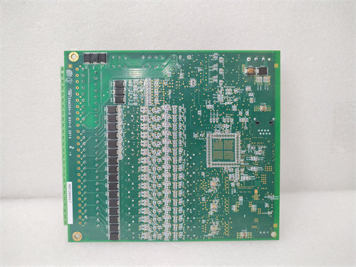
- Microprocessor and Logic: The board contains a microprocessor and multiple $\text{PROM}$ (Programmable Read-Only Memory) modules to execute the digital logic, condition the signals, and communicate the data across the system.
- $\text{IONET}$ Communication: It communicates its processed digital data via the $\text{IONET}$ (Input/Output Network) to the main control processors (the $\text{R}$, $\text{S}$, and $\text{T}$ cores) for use in the overall turbine control software.
📍 Location and Specifications
- Series: $\text{GE Speedtronic Mark V}$ Turbine Control System.
- Functional Acronym: $\text{TCDA}$ (Digital I/O Board).
- Typical Location: Found in the dedicated Digital $\text{I/O}$ Cores of the $\text{Mark V}$ panel, often designated as $\text{Q11}$, $\text{Q21}$, or $\text{Q51}$.
- Hardware:
- Connectors: Features several connectors ($\text{JP}$, $\text{JQ}$, $\text{JR}$, $\text{JO1}$, $\text{JO2}$, $\text{JX1}$, $\text{JX2}$) for power distribution, contact inputs from terminal boards, output to relay boards, and $\text{IONET}$ communication.
- Jumpers: Includes hardware jumpers ($\text{J1}$ to $\text{J8}$) for configuration, such as setting the $\text{IONET}$ termination resistors ($\text{J2}$ and $\text{J3}$) and the board’s address.
- Indicators: Typically includes an $\text{LED}$ block for diagnostics.
The $\text{DS200TCDAG1B}$ is essential for the $\text{Mark V}$ system to correctly sense the status of plant equipment and issue the necessary commands to actuate valves, motors, and other digital devices to control the turbine.