+86 15340683922
 +86 15340683922
الوصف
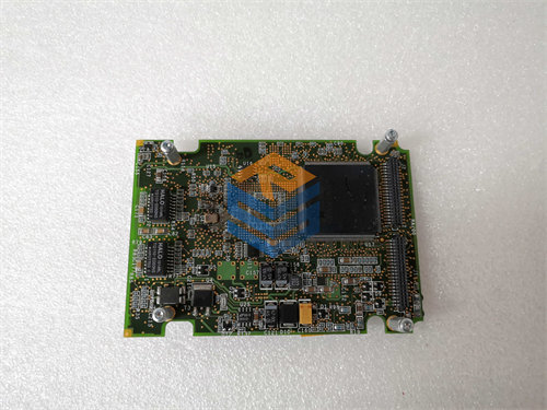
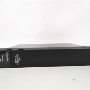
The GE DS200TCDAH1BJE is a Digital I/O (Input/Output) Board designed for use within the GE Speedtronic Mark V Series Turbine Control Systems.1
Its main purpose is to manage the flow of digital (discrete) signals between the main control system and the physical equipment in the field, making it a crucial component for industrial automation and turbine management.2
💻 Function and Location
The board’s functional acronym is TCDA, indicating it is responsible for handling digital contact data.3
- Signal Processing: The TCDA board takes digital contact input signals from associated terminal boards (like the DTBA and DTBB) via 50-pin connectors.4 It then conditions these signals, time-tags any change of state, and prepares them for the main processor.5
- Output Control: It manages and transmits contact output signals (for controlling relays and solenoids) to other system boards, such as the TCRA boards, which then drive the physical actuators.6
- Communication: The processed signals are efficiently communicated to the rest of the control system over the internal network, the IONET, typically through its JX1 and JX2 connectors.7
- Location: The DS200TCDAH1BJE is typically installed in the digital I/O cores (8$\text{Q11}$ and 9$\text{Q51}$) of a Mark V LM (Land-Marine) turbine control system.10
📋 Key Hardware and Configuration
The DS200TCDAH1BJE PCB has several components that allow for its specific function and configuration:11
- Connectors: It is equipped with two 50-pin ribbon connectors (12$\text{JQ}$ and 13$\text{JR}$) for high-density I/O connections to the terminal boards, and two 3-pin connectors (14$\text{JX1}$ and 15$\text{JX2}$) for IONET communication.16
- LED Indicators: It includes one LED (CR9) visible from the side of the board, which typically lights up green to indicate power is being received and flashes during processing.17 It also has a block of 10 LEDs for additional status and diagnostic feedback.18
- Jumpers: The board features 8 hardware jumpers (labeled 19$\text{JP1}$ through 20$\text{JP8}$).21 These jumpers are critical for configuring the board to match the specific requirements and location within the site’s control system.22 When replacing the board, the jumper settings must be correctly matched to the old unit.
- Protection: Like many GE Mark V boards, it is generally protected with a conformal coating to guard against harsh industrial environments.23