+86 15340683922
 +86 15340683922
الوصف
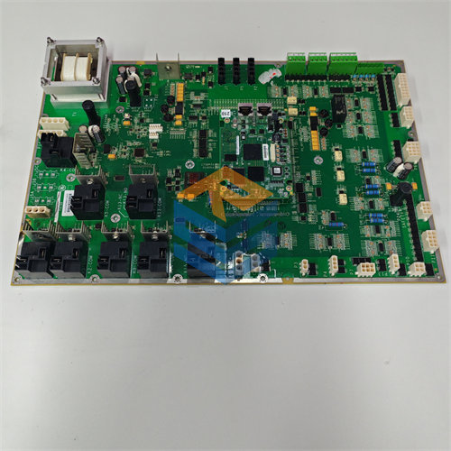
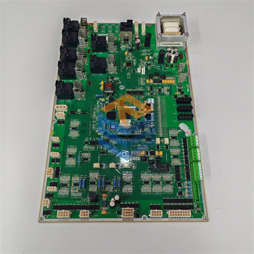
The GE DS200TCEAG2B is an Emergency Overspeed Board (Functional Acronym: TCEA) for the GE Speedtronic Mark V Gas Turbine Control System, specifically often associated with the Mark V LM Series (for aero-derivative turbines).1
Its primary function is to serve as an independent, high-speed safety processor to protect the turbine from overspeed and other critical failure conditions.2
🛑 Function and Location
The DS200TCEAG2B is a critical component that enforces the highest level of safety on the turbine.3
- Emergency Overspeed Trip: Its main job is to constantly monitor the turbine’s rotational speed, particularly the high-pressure (HP) and low-pressure (LP) shafts.4 If the speed exceeds a preset emergency limit, the board will quickly de-energize the Emergency Trip Relays (ETRs) on the Turbine Trip Board (TCTG) to shut down the unit.5
- Flame Detection: It also processes signals for flame detection and can initiate a trip if it detects a flame-out condition in the combustor.6
- Location: The board is mounted in the Protective Core (7$\text{P1}$) of the Mark V panel.8 In a typical Triple Modular Redundancy (TMR) system, three TCEA boards (labeled X, Y, and Z) are used to ensure no single component failure can prevent a critical trip.9
Redundancy and Voting
The TCEA boards work together to provide fault tolerance:
- Input Conditioning: The boards receive signals from the speed magnetic pickups, often routed through the PTBA terminal board.10
- Data Transmission: The TCEA boards condition and scale the signals, then transmit the data over the IONET to the R1 core.11
- Voted Trip: The 12$\text{I/O}$ Engine performs a median selection (voting) on the values from the three TCEA boards.13 For trip signals, the TCEA sends an emergency trip request to the TCTG board, which then uses 2/3 relay driver-level voting to finalize the trip, ensuring exceptional reliability.14
🛠️ Hardware and Configuration
The DS200TCEAG2B is microprocessor-based, utilizing an Intel 80196 microprocessor to execute the safety firmware and logic.15
| Component | Purpose |
| PROM Modules | Stores the firmware and operating instructions. These are typically moved from the old board to a replacement board. |
| Jumpers ($\approx$ 30) | Used to configure the board’s specific settings, including: IONET address ($\text{J4, J5, J6}$), IONET termination resistors ($\text{J2, J3}$), and confirming Overspeed trip frequency settings ($\text{J8-J27}$). |
| Fuses (3) | Provides protection for the circuit against voltage spikes and overcurrent. |
| LEDs | A green LED indicates power and processing status (flashing indicates normal operation). |
| Connectors | Dedicated bayonet connectors (J7, JK, JL, JW, JX1/JX2) interface with the power supply, the TCEB (signal expansion), and the TCTG (trip signals). |
The “G2” in the part number ($\text{DS200TCEAG2B}$) signifies a later generation or revision of the board compared to the $\text{G1}$ version, often incorporating minor component updates or design refinements.