+86 15340683922
 +86 15340683922
الوصف
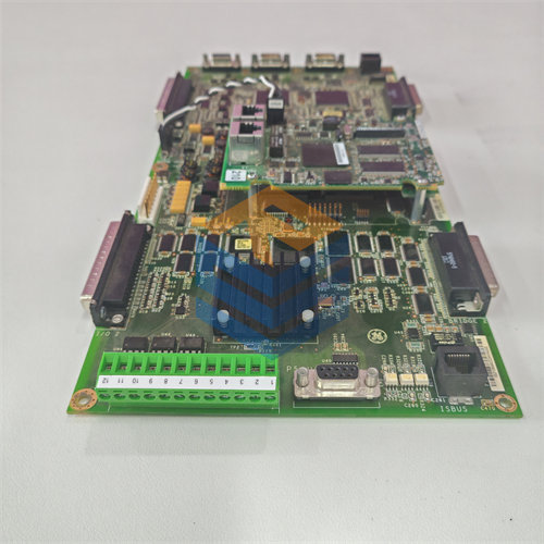
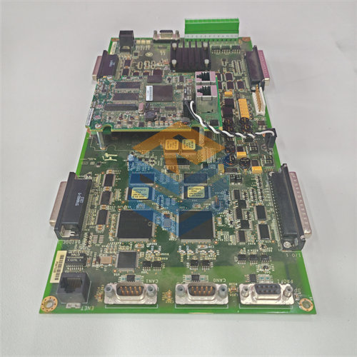
The GE DS200TCEBG1 is a Protective Termination Expander Board (Functional Acronym: TCEB) used in the General Electric Speedtronic Mark V Turbine Control System.1
This board is a vital interface component located in the protective core (2$P1$) of the Mark V panel.3 It acts as a central hub for safety-related input signals before they are distributed to the protective processor boards.4
🛠️ Key Function and Signal Routing
The DS200TCEBG1 (TCEB) board’s main role is to facilitate the routing, conditioning, and scaling of critical signals for the Mark V’s protective and control logic.5
1. Protective Signal Management
The TCEB serves as an intermediary for signals related to the most critical turbine safety functions:6
- Emergency Overspeed and Flame Detection: It receives signals for emergency overspeed (from magnetic pickups) and flame detection (from UV flame detectors) from the PTBA Terminal Board.7
- Signal Distribution: The TCEB then passes these raw signals onto the three redundant Emergency Overspeed Boards (TCEA boards) for processing and trip-logic voting.8
2. Voltage and Current Signal Scaling
The board also handles crucial electrical measurements for the generator and bus:9
- CT and PT Scaling: It scales (adjusts and conditions) the signals from the Current Transformers (CTs) and Potential Transformers (PTs).10
- Transmission to Control Core: These scaled signals (representing line current, generator voltages, and bus voltages) are then transmitted to the Control Core (R5) to be used by the TCCB (Control Core Board) for monitoring and control functions.11
3. Power and Alarm Functions
The TCEB manages power distribution for the flame detectors and provides an audible warning:
- Flame Detector Power: It conditions and routes the 335 V DC power required for the UV flame detector devices.12
- Alarm Horn: The audible alarm horn for the Mark V LM version is typically mounted directly on the TCEB board.13
🔌 Connectors and Interfacing
The TCEB board features numerous connectors to interface with other boards in the Mark V system:14
| Connector | Interfacing Board | Signal Function |
| JKX, JKY, JXZ | TCEA Boards | Carries overspeed and flame detection signals. |
| JMP | TCCB Board (R5 Core) | Transmits the scaled CT and PT signals. |
| JV | PTBA Terminal Board | Receives the raw CT and PT signals. |
| JU | PTBA Terminal Board | Receives magnetic pickup and flame detection signals. |
| JVA | PTBA Terminal Board | Sends the 335 V DC power for the flame detectors. |
Note: The DS200TCEBG1 is an Expander Board, meaning it provides the necessary connection points and minor conditioning circuitry but does not contain a microprocessor or firmware for complex logic execution, unlike the TCEA Emergency Overspeed Board.