+86 15340683922
 +86 15340683922
الوصف
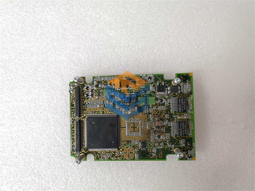
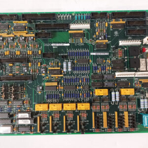
The GE DS200TCEBG1B Protective Termination Expander Board (TCEB) is a specific revision of a key circuit board used in the General Electric Mark V Speedtronic Turbine Control System.1
The suffix G1B indicates that this is the base version of the board with a single functional revision “B” applied to the original design (G1).2 Its role is crucial for safety and monitoring functions within the turbine control panel.3
💡 Core Functionality
The Protective Termination Expander Board (TCEB) serves as a vital signal conditioning and routing interface, primarily handling the input/output for critical protection and monitoring signals.4
- Signal Scaling and Conditioning: The main function is to scale the high-voltage signals coming from the Potential Transformers (PT) and high-current signals from the Current Transformers (CT).5 These conditioned signals are used by the TCCB (Turbine Core Control Board) for calculating generator voltage, bus voltage, and line current.6
- Protection Signal Routing: It acts as a dedicated pathway for critical safety signals, including those for emergency overspeed magnetic pick-up and flame detection.7 These signals pass from the PTBA terminal board through the TCEB to the TCEA (Emergency Overspeed) boards for processing in the system’s Triple Modular Redundancy (TMR) setup.8
- Power and Alarm: It conditions and routes the 335 V DC power needed for the UV flame detector devices.9 It also holds the audible alarm horn (on Mark V LM variants) to signal fault conditions.10
- Non-Configurable: This board generally has no software configuration and no hardware jumpers for system configuration (the alarm horn jumper, if applicable, is usually on the PTBA terminal board).11
🛠️ Key Hardware Features
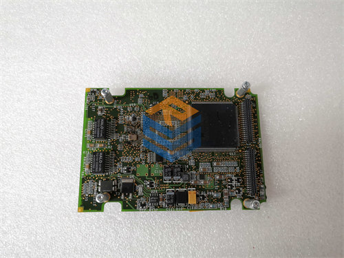
The physical construction of the DS200TCEBG1B includes multiple connectors for its signal routing duties:12
| Component / Connector | Quantity | Purpose in Mark V System (Examples) |
| Signal Transformers | 4 | Improves signal compatibility and isolation. |
| Bayonet Connectors | 3 | Used for connecting certain high-speed signals (labeled JWX, JWY, JWZ). |
| Ribbon Cable Connectors | 3 (20-pin) | Routes signals (like flame detection and magnetic pick-up) to TCEA boards (JKX, JKY, JKZ). |
| Other Connectors | 1 (26-pin) & 4 (10-pin) | Includes connectors like JMP (PT/CT signals to TCCB) and JV (PT/CT signals from PTBA). |
| Location | P1 Core | The typical slot location within the Mark V control panel. |
The DS200TCEBG1B is considered an integral part of the common circuits (EOS) for the turbine protection system.13