+86 15340683922
 +86 15340683922
الوصف
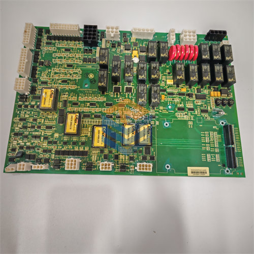
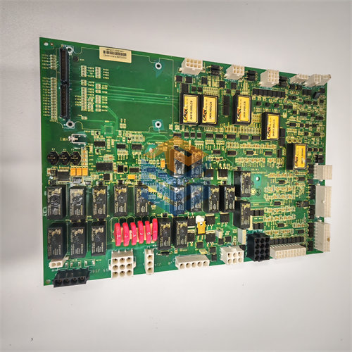
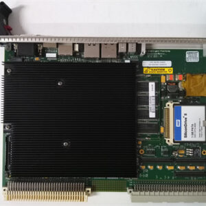
The GE DS200TCQAG1 RST Analog I/O Board is an essential printed circuit board ($\text{PCB}$) used in the General Electric (GE) Speedtronic Mark V Turbine Control System.
The designation TCQA stands for the functional description of the board, which is the Analog Input/Output ($\text{I/O}$) Board. The “G1” in the part number indicates it is the original version of this board series for the Mark V system, without any letter-designated revisions (like G1A or G1B).
💡 Primary Function in the Mark V System
The DS200TCQAG1 board’s main role is to act as the interface between the control system’s digital logic and the continuous, real-world analog signals from the gas or steam turbine machinery.
- Signal Conditioning and Scaling: Its primary task is to scale and condition the numerous analog signals coming from field devices (sensors) before they are sent to the Mark V control processors ($\text{R1}$, $\text{R2}$, $\text{R3}$ cores).
- Analog-to-Digital Conversion: It performs the necessary conversion of analog sensor inputs into digital values that the control system can use.
- Digital-to-Analog Conversion: It converts digital commands from the control system back into analog signals to drive control devices.
📊 Key Analog Signals Processed
The $\text{TCQA}$ board handles a comprehensive range of analog inputs and outputs critical for turbine control and protection:
| Signal Type | Function / Application |
| Thermocouple Inputs | Measures temperatures (e.g., combustion or exhaust) for monitoring and control. |
| LVDT/LVDR Inputs | Reads position feedback from actuators, such as servo valves, for precise fuel control. |
| Vibration Inputs | Monitors turbine casing and bearing vibration for protection and maintenance. |
| $4-20 \text{ mA}$ Inputs/Outputs | Standard industrial current loops for measuring and controlling pressure, flow, and level signals. |
| Servo Valve Outputs | Provides the analog control signal to the servo actuators that meter fuel or steam flow. |
| Pulse Rate Inputs | Conditions signals from magnetic pickups (MPUs) for speed/overspeed protection. |
| Voltage Inputs | Handles general $\pm 10 \text{ VDC}$ inputs. |
🧩 Hardware Features
The DS200TCQAG1 is a large circuit board that includes the following major hardware components:
- Microprocessor: It utilizes an 80196 microprocessor to manage the data flow and execute conditioning logic.
- Connectors: It features multiple connectors (including 34-pin and 40-pin types) for communication with other boards in the Mark V cabinet, specifically:
- Terminal Boards ($\text{TB}$): Connects to boards like $\text{TBQA}$ (for thermocouples) and $\text{TBQC}$ (for $4-20 \text{ mA}$ and $\text{LVDT/R}$ signals) to receive field wiring inputs.
- Data Bus ($\text{3PL}$): Connects to the main control processors to send conditioned data.
- LEDs and Jumpers: It has 6 $\text{LED}$ lights for status indication and multiple jumpers for hardware configuration (e.g., selecting milliamp output ranges or enabling test functions).