
 +86 15340683922
 +86 15340683922
الوصف
That is an excellent question, focusing on a slightly different revision of the GE Mark V Analog I/O board.
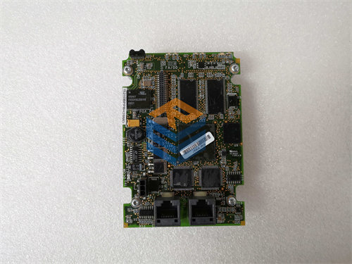
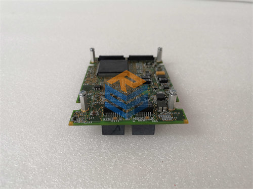
The GE DS200TCQAG2B is an RST Analog I/O Card (TCQA) for the GE Mark V Speedtronic Turbine Control System. The primary difference from the “G1” versions lies in the internal hardware configuration, often relating to connector layout, component density, or a minor functional update. The change from “G1” to “G2” is a significant revision level within the product series.
Here is a detailed breakdown of the board, highlighting its function and key specifications:
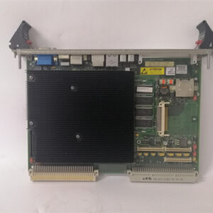
🛠️ Product Profile: GE DS200TCQAG2B (TCQA G2 Revision)
The DS200TCQAG2B is a high-density, multi-function Printed Circuit Board (PCB) responsible for handling the most critical analog signals within the Mark V system’s control architecture.
| Specification | Detail |
| Functional Acronym | TCQA (Analog I/O Card) |
| Control System | GE Mark V Speedtronic |
| Revision Level | G2 (Indicates a major hardware revision from G1) |
| Hardware Suffix | B (A specific minor revision/Bill of Materials) |
| Architecture | RST (Used in Triple Modular Redundancy – TMR) |
| Primary Function | High-precision signal scaling, conditioning, and Analog-to-Digital (A/D) / Digital-to-Analog (D/A) conversion. |
1. Role in TMR Architecture
Like all Mark V RST boards, the DS200TCQAG2B operates in one of the three redundant control cores (R, S, or T). Its output signals are continuously compared with the signals from the other two cores to ensure data integrity and system reliability through the patented Voter Logic. This prevents a single hardware failure from causing a turbine trip or erroneous control action.
2. Supported Signal Types (Analog Inputs)
The TCQA board is designed to interface directly with the most sensitive turbine sensors:
- Thermocouples (T/C): The board includes circuitry for Cold Junction Compensation (CJC) to ensure highly accurate temperature readings, crucial for combustion and over-temperature protection.
- LVDT/LVDR Inputs: It processes signals from Linear/Rotary Variable Differential Transformers to monitor the precise position of fuel or steam control valves (e.g., stroke position).
- 4-20 mA Inputs: Standard industrial current loops from pressure, flow, and level transmitters.
- Voltage Inputs: Various DC voltage inputs used for general signal monitoring.
3. Analog Control Outputs
The board generates the necessary high-resolution control signals to drive field actuators:
- Servo Valve Outputs: Provides the proportional current or voltage required to operate servo valves. This directly influences fuel or steam flow to the turbine, enabling precise speed and load control.
- 4-20 mA Outputs: Used to transmit control setpoints to external devices or proportional actuators.
4. G2 Revision Considerations
The “G2” revision usually signifies one or more of the following key changes compared to “G1” versions:
- Component Update: Replacement of obsolete or legacy chips with newer, more reliable, or higher-density components.
- Connector Mapping: Minor changes in the pinout or function of certain connectors (though the main 3PL data bus connection remains consistent).
- Enhanced Filtering: Potential improvements to the on-board signal conditioning and filtering to better reject electrical noise (EMI/RFI).
5. Interfacing and Connectivity
The DS200TCQAG2B connects to other Mark V core components via specific multi-pin connectors:
- 3PL Connector: The main data bus connection that links the TCQA board to the STCA (System Turbine Control Assembly) or I/O Engine board, where conditioned signals are exchanged with the CPU/Controller.
- JA/JB/JD/JE/JG Connectors: Used to interface with the specific Terminal Boards (TBQA/TBQC) mounted on the cabinet wall, which provide the physical screw terminals for connecting the field wiring (sensors and actuators).