+86 15340683922
 +86 15340683922
الوصف
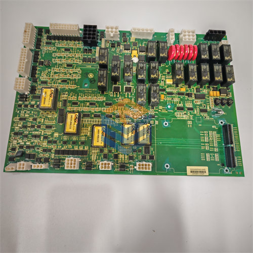
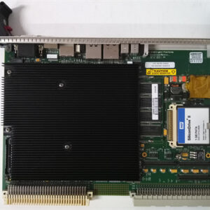
GE DS200TCQBG1BBA, and based on the available information, it is most accurately identified as an RST Extended Analog I/O Board. While it’s sometimes colloquially called an “Overflow Card,” its main functional designation is TCQB, which is distinct from the TCQC board typically labeled as the “RST Overflow Board.”
To ensure accuracy, let’s confirm the primary function associated with the TCQB designation in this specific revision.
The GE DS200TCQBG1BBA is an RST Extended Analog I/O Board for the GE Mark V Speedtronic Turbine Control System, often referred to by its functional acronym TCQB.1
While sometimes colloquially referred to as an “Overflow Card,” its specialized function goes beyond basic I/O expansion, focusing heavily on critical turbine signals.
⚙️ Board Profile: DS200TCQBG1BBA
| Specification | Detail |
| Functional Acronym | TCQB (Turbine Control Q/R/S/T Board) |
| System Series | GE Mark V Speedtronic Turbine Control |
| Board Type | RST Extended Analog I/O Board |
| Hardware Revision | G1B (First generation, ‘B’ functional revision) |
| Artwork/Component Revision | BA (Specific minor revision codes) |
| Architecture | RST (Triple Modular Redundancy – TMR) |
| Primary Function | Processes pulse rate (speed) signals and specialized analog/vibration inputs. |
1. Primary Functions (TCQB)
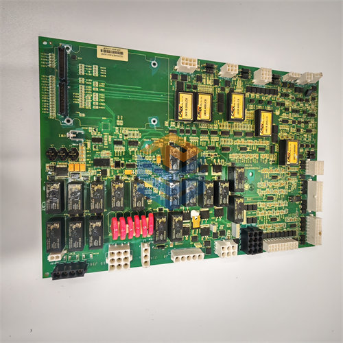
The TCQB board is an optional, multifunction I/O card installed in the R, S, and T cores to handle specialized or “extended” I/O, including:2
- Proximitor Inputs: Processes signals from proximity sensors (proximitors) used for shaft vibration and position monitoring, which is critical for turbine protection.3 The card contains circuitry to condition and scale these signals.4
- Speed/Pulse Rate Inputs: It is configured to receive and condition high-speed pulse rate signals from magnetic pickups or proximity probes used for turbine speed control and overspeed protection.
- LVDT/LVDR Inputs: It supports inputs from Linear/Rotary Variable Differential Transformers used for valve position feedback in some applications.5
- Regulator Milliamp Outputs: It often provides a limited number of specialized current outputs (e.g., 6$4-20 \text{ mA}$) for controlling devices like servo regulators.7
2. RST Redundancy
The RST designation is central to the board’s role. Three identical $\text{DS200TCQBG1BBA}$ cards (one in the R core, one in the S core, and one in the T core) operate in parallel.
- Each board independently reads its sensors.
- The system uses Software Implemented Fault Tolerance (SIFT), or voter logic, to compare the three signals and use the median value, ensuring system reliability against a single card or sensor failure.
3. Hardware & Replacement
The board is a complex circuit card that typically includes a Programmable Logic Device (PLD) and requires EPROM modules (Erasable Programmable Read-Only Memory) to be installed separately.8 The EPROMs contain the firmware and application logic required for the board to process its specific I/O signals, and must be correctly transferred from the old board to a replacement.9