+86 15340683922
 +86 15340683922
الوصف
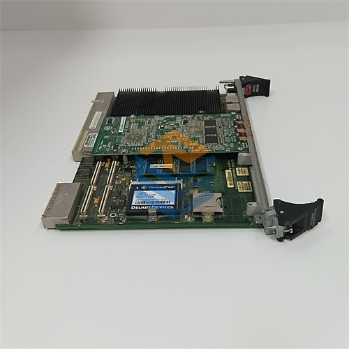
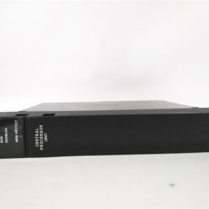
The GE DS200TCQCG1A is an RST Overflow Board (also known as a Digital I/O Expander Board) designed for the GE Mark V Speedtronic Turbine Control System.
This board plays a crucial role in providing additional I/O capacity, primarily for digital signals, which has led to the common functional designation “Overflow Board.”
🛠️ Product Profile: DS200TCQCG1A
| Specification | Detail |
| Functional Acronym | TCQC (Turbine Control Q/R/S/T Board, typically Digital/Expander I/O) |
| System Series | GE Mark V Speedtronic Turbine Control |
| Board Type | RST Overflow Board / Digital I/O Expander |
| Hardware Revision | G1A (First major hardware revision with a minor update) |
| Architecture | RST (Triple Modular Redundancy – TMR) |
| Primary Function | Provides expanded capacity for digital inputs/outputs (I/O) and may handle certain low-density analog signals, often used when the standard I/O banks are insufficient. |
1. The “Overflow” Function
The term “Overflow” is descriptive of the board’s purpose. It is installed to supplement the I/O capacity of the main Mark V I/O processor boards (like the STCA or UCC) when the total number of sensors, switches, or solenoids connected to the turbine package exceeds the limits of the primary I/O boards.
- Expanded Digital I/O: The TCQC is often configured to receive and transmit additional $\text{DC}$ logic signals (digital inputs and outputs) for sequence logic, auxiliary equipment, and general status monitoring.
2. TCQC Designation
The $\text{TCQC}$ acronym, similar to $\text{TCQA}$ and $\text{TCQB}$, indicates that the board resides in the R, S, and T cores. Unlike the TCQA (Analog) or TCQB (Pulse/Extended Analog), the TCQC is most frequently associated with:
- Digital I/O: Discrete contacts for start/stop permissive, limit switches, solenoid valve commands, etc.
- Voter/Transfer Logic: It may contain circuitry that aids the main processor in managing the voting process or handling data transfer for the signals it processes.
3. RST Redundancy
As an $\text{RST}$ board, three $\text{DS200TCQCG1A}$ cards are installed, one in each core. Each board independently acquires its signals, and the system compares the three redundant signals to maintain fault-tolerant operation. For digital signals, the voting process is a simple comparison (e.g., 2-out-of-3 must agree).
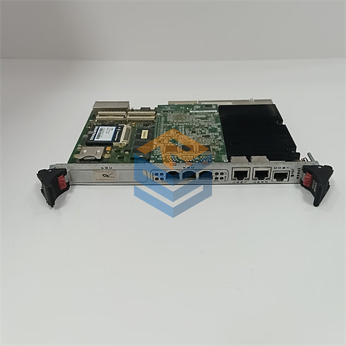
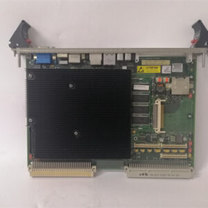
4. Hardware and Connectivity
The board interfaces with the system processor via the backplane and connects to the turbine’s field wiring through dedicated terminal boards (TBQC or similar, depending on the configuration). It typically contains:
- Connectors: Multi-pin connectors for signal interface.
- Jumpers: Used for hardware configuration, setting I/O type, or enabling/disabling certain functions.
- EPROM/Firmware: Contains its own firmware for processing its assigned signals.