
 +86 15340683922
 +86 15340683922
الوصف
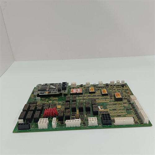
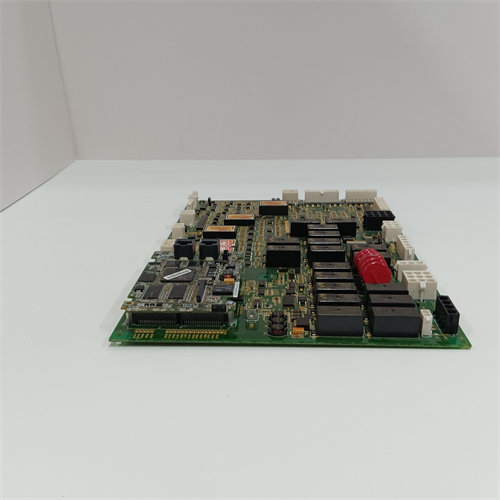
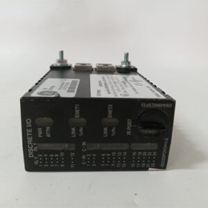
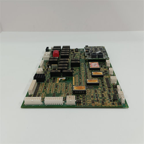
The GE DS200TCQCG1ADB is a highly specific circuit board known as an Analog I/O Expander Board (or RST Overflow Board) for the GE Mark V Speedtronic Turbine Control System.
This board, identified by the functional acronym TCQC, is designed to augment the input/output capacity of the main Mark V controller, primarily focusing on supplementing digital and, in this configuration, certain extended analog signals.
Here is a detailed breakdown of this component:
🛠️ Product Profile: DS200TCQCG1ADB
| Specification | Detail |
| Functional Acronym | TCQC (Turbine Control Q/R/S/T Board) |
| System Series | GE Mark V Speedtronic Turbine Control |
| Board Type | Analog/Digital I/O Expander Board (Overflow Board) |
| Hardware Revision | G1 (First major hardware design) |
| Revision Suffix | ADB (Specific component/artwork revision code) |
| Architecture | RST (Triple Modular Redundancy – TMR) |
| Primary Function | Provides expanded digital and potentially low-density analog I/O capacity when the main I/O boards (like TCQA/TCQB) are insufficient. |
1. Expander Board Role
The TCQC board fills the need for extra I/O points beyond the standard capacity of the Mark V system. While the TCQC designation is often associated with digital (discrete) signals, the name “Analog IO Expander Board” confirms that this specific revision is configured to handle:
- Digital I/O: The bulk of the signals likely consists of discrete status inputs (limit switches, equipment status) and discrete outputs (solenoids, relays).
- Low-Density Analog: It handles a limited number of analog signals that “overflow” the capacity of the primary analog input board (TCQA).
2. RST Redundancy
As an RST board, three $\text{DS200TCQCG1ADB}$ cards operate simultaneously in the R, S, and T control cores.
- Fault Tolerance: Each board processes its signals independently. The central processing unit (CPU) employs voting logic (often 2-out-of-3) to ensure that control decisions are based on validated data, maintaining system uptime even if one board fails.
3. The Revision Code G1ADB
The full revision code $\text{G1ADB}$ is crucial for maintenance and replacement:
- Hardware Mapping: The specific revision code dictates the exact configuration of components, jumpers, and signal mapping on the board.
- Firmware Compatibility: The system’s application software and the firmware (PROMs) on the central controller boards are configured to communicate with and expect the signal characteristics of the $\text{G1ADB}$ revision. A mismatch can lead to communication errors or incorrect signal scaling.
4. Connectivity
The board connects to the field wiring (sensors and actuators) via a dedicated terminal board, which provides the screw terminals for the physical wires.