
 +86 15340683922
 +86 15340683922
الوصف
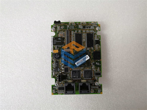
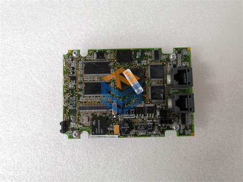
The GE DS200TCQCG1BHF is an Analog I/O Expander Board (also commonly called an RST Overflow Board or TCQC) designed for the GE Mark V Speedtronic Turbine Control System.1
This board is a critical component for managing the signals that “overflow” the capacity of the main analog and digital I/O boards, particularly those related to critical turbine functions.2
⚙️ Board Profile: DS200TCQCG1BHF
| Specification | Detail |
| Functional Acronym | TCQC (Turbine Control Q/R/S/T Board) |
| System Series | GE Mark V Speedtronic Turbine Control System |
| Board Type | Analog I/O Expander Board / RST Overflow Board |
| Hardware Revision | G1B (First major revision, second functional iteration) |
| Artwork/Component Revision | HF (Specific minor revision codes) |
| Architecture | RST (Triple Modular Redundancy – TMR) |
| Key Functions | LVDT/LVDR Excitation, Servo Drive Outputs, Pulse Rate Inputs, and Megawatt Transducer Scaling. |
1. Primary Functions
The TCQC board has a diverse role, handling a variety of signals that require specific conditioning or are supplementary to the main I/O cards (TCQA, TCQB).3 Its primary duties include:
- LVDT/LVDR Excitation: The board is essential for generating the AC excitation signals required to power Linear Variable Differential Transformers (LVDTs) and Rotary Variable Differential Transformers (LVDRs), which are used to measure the position of control valves.4
- Servo Drive Outputs: It processes the current signals for servo valves or other regulators, often scaling and conditioning signals received from the TCQA board before sending them to the final output drivers.5 It may also contain safety relays (like “suicide relays”) to force the servo valves to a safe position during a trip.
- Analog Scaling: It scales and conditions various analog current signals (e.g., 6$4-20 \text{ mA}$ inputs), such as those from a megawatt transducer, before routing the data to the main processor.7
- Pulse Rate Inputs: It handles and conditions certain pulse rate signals (like high-pressure shaft speed or liquid fuel flow) that are not processed by the main speed input card (TCQB).8
2. RST Redundancy
As an RST board, three 9$\text{DS200TCQCG1BHF}$ cards are used, one in the 10$\text{R}$, 11$\text{S}$, and 12$\text{T}$ control cores.13 This TMR architecture provides fault tolerance:
- Each board receives the same input signals independently.
- The three core processors compare the data, and if one signal deviates, the system ignores the faulted value and continues running based on the two good signals (2-out-of-3 voting). This allows the turbine to remain online even if one TCQC board fails.
3. Installation Notes
The 14$\text{DS200TCQCG1BHF}$ is highly customizable and contains a large number of jumper switches (sometimes 37 or more).15 When replacing this board, it is critical to exactly duplicate the jumper settings from the old board to the new board, as these jumpers define the specific I/O configuration and signal ranges for that particular turbine control application.16