+86 15340683922
 +86 15340683922
الوصف
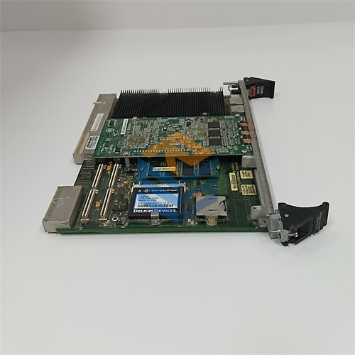
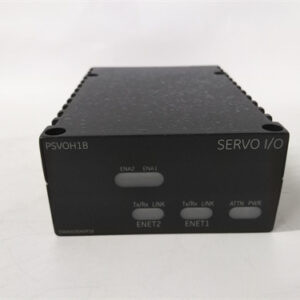
The GE DS200TCQCG1BJF is an Analog I/O Expander Board designed for the GE Mark V Speedtronic Turbine Control System.1
It is part of the system’s core control architecture, often serving as an “overflow” or auxiliary board to handle critical analog and pulse signals that exceed the capacity of the main I/O boards.2
🚀 Key Features of the DS200TCQCG1BJF (TCQC Board)
The DS200TCQCG1BJF board, often designated as the TCQC (Turbine Control Q/R/S/T Board), is essential for expanding the I/O capacity and providing excitation for key turbine sensors and actuators.3
1. System and Function
| Feature | Detail |
| System | GE Mark V Speedtronic Gas & Steam Turbine Control System |
| Functional Role | Analog I/O Expander Board / RST Overflow Board |
| Architecture | RST (Triple Modular Redundancy – TMR) |
| Part Number Codes | $\text{G1B}$ (Functional Revision), $\text{JF}$ (Artwork/Assembly Revision) |
2. Signal Handling and I/O Expansion
The board primarily focuses on scaling, conditioning, and routing signals critical to turbine operation and protection:4
- LVDT/LVDR Excitation: The board generates the necessary 5$\text{AC}$ excitation voltage for Linear Variable Differential Transformers (LVDTs) and Rotary Variable Differential Transformers (LVDRs), which are used to measure the position of turbine control valves.6
- Servo Valve Control: It contains circuitry to process and scale the current signals for servo valve regulators that drive the turbine’s hydraulic actuators.7 This includes logic for maximum current range and feedback scaling, often configurable via jumpers.8
- Analog Input Scaling: It handles scaling and conditioning of specific 9$\text{mA}$ input signals, such as those from a megawatt transducer.10
- Pulse Rate Inputs: It processes certain pulse rate signals, like high-pressure shaft speed or liquid fuel flow, integrating them into the control system.11
3. Hardware Configuration
The specific configuration of the $\text{DS200TCQCG1BJF}$ is determined by its on-board components:
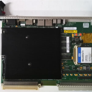
- Jumpers: This board is equipped with a significant number of hardware jumpers (typically 24 or more).12 These jumpers are used to set parameters such as the servo output current range and feedback scaling.13 Crucially, all jumper settings must be copied exactly from the old board when performing a replacement.14
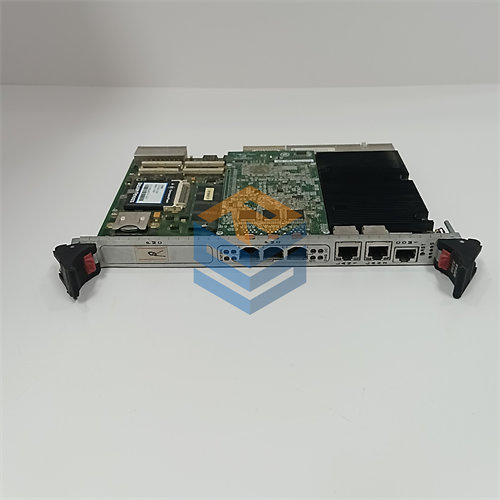
- Connectors: The board uses multiple high-density pin connectors (e.g., three 40-pin and three 34-pin connectors) to interface with other I/O boards within the Mark V control core via ribbon cables.15
4. Safety and Redundancy
As an $\text{RST}$ board, the $\text{DS200TCQCG1BJF}$ operates in all three redundant control cores ($\text{R}, \text{S}, \text{T}$) to ensure no single board failure can cause a trip. It also contains relays (including “suicide relays”) which are integral to the turbine’s emergency trip and fuel shut-off logic.16