
 +86 15340683922
 +86 15340683922
الوصف
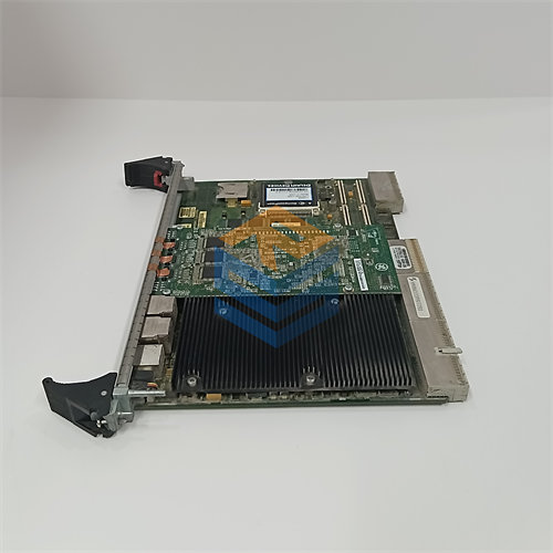
The GE DS200TCQFG1ACB is a specific revision of an Analog I/O Extender Card for the GE Mark V Speedtronic Turbine Control System.
This board is a variant of the TCQF family, known functionally as the TC2000 Analog I/O Extension Card. The multiple letters in the part number indicate a highly customized or revised version of the original design.
| Part Segment | Significance |
| DS200 | Component for the GE Mark V Series. |
| TCQF | Functional Acronym: Turbine Control Q/R/S/T Core Card, typically for Analog I/O Extension. |
| G1 | Group/First Major Revision. |
| A, C, B | Subsequent Functional and/or Artwork Revisions. |
⚙️ Function and Application Context
The DS200TCQFG1ACB is a member of the I/O processing boards ($\text{TCQ…}$) that reside in the redundant $\text{R, S,}$ and $\text{T}$ control cores of the Mark V panel.
1. Analog I/O Expansion and Scaling
Its core purpose is to extend the analog input/output capabilities of the main control processors.
- Signal Handling: It is designed to handle and condition a variety of analog signals, such as $4-20 \text{ mA}$ inputs/outputs, voltage inputs, and possibly some pulse inputs, which are essential for regulating various control elements.
- Conditioning and Filtering: The board scales, filters, and prepares these signals for reliable use by the digital control logic residing on other processor boards.
2. Associated Control Systems
While installed in a Mark $\text{V}$ system, the functional name “$\text{TC2000}$ Analog I/O Extension Card” suggests a strong association with the $\text{GE EX2000}$ or $\text{TC2000}$ series of drives or exciter controls. This board is often found in Mark $\text{V}$ panels that integrate gas turbine control with generator excitation or electric drive control.
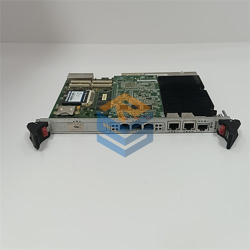
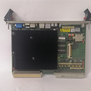
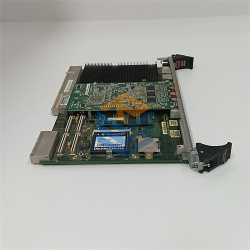
3. Hardware Configuration
Like other $\text{TCQ}$ boards, the $\text{DS200TCQFG1ACB}$ is characterized by:
- Jumpers: Multiple onboard jumpers allow for hardware configuration, setting parameters like current ranges, position feedback scaling, and regulator time constants.
- Connectors: It uses ribbon cables connected via multi-pin connectors (like the $34$-pin and $50$-pin connectors) to interface with the terminal boards where the field wiring is connected, and with the main processor boards.
The numerous revision codes ($\text{G1ACB}$) indicate that this board has undergone several hardware or firmware updates since its original design ($\text{G1A}$) to improve its performance, fix issues, or accommodate different field application requirements.