+86 15340683922
 +86 15340683922
الوصف
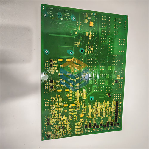
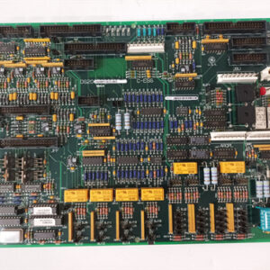
The GE DS200TCTGG2A Turbine Trip Board is a safety control module for the General Electric Speedtronic Mark V Gas Turbine Control System.1 It is functionally identical to the $\text{DS200TCTGG1A}$ series but is specifically designated for use with the TC2000 processor in applications involving heavy-duty or aero-derivative gas turbines.
It is sometimes referred to as the TC2000 Trip Module.2
⚙️ Key Function and Application
The primary role of the $\text{DS200TCTGG2A}$ (or $\text{TCTG}$) board is to serve as the hardware-level safety gate for the turbine.
- Emergency Trip Execution: It provides the physical relays necessary to de-energize the master protective circuit, which quickly removes hydraulic pressure from the turbine’s fuel or steam stop valves, causing them to close and shut down the unit.
- Relay Types: It houses two critical sets of trip relays:3
- Primary Trip Relays (4$\text{PTRs}$): Initiated by the main control sequence program and communication faults.5
- Emergency Trip Relays ($\text{ETRs}$): Crucial for the redundant (TMR) protection core. The ETRs typically execute a trip based on a two-out-of-three vote from the 6$\text{TCEA}$ boards (7$\text{X}$, 8$\text{Y}$, and 9$\text{Z}$ processors) to protect against critical faults like overspeed.10
- Application: The ‘11$\text{G2}$‘ in the part number often indicates its use with specific processor models (like the TC2000)12 or specific types of turbines, typically large heavy-duty or aero-derivative gas turbines.
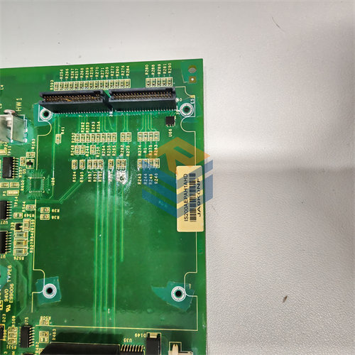
🏗️ Hardware and Connections
The physical construction of the $\text{DS200TCTGG2A}$ is robust, designed to withstand industrial environments, and features specific components for its safety role:
- Relays: It is populated with 21 plug-in relays (prefixed with ‘K’), which are the mechanical switching elements that carry out the trip and synchronization commands.13
- Connectors:
- 3 x 50-pin Connectors ($\text{JLX, JLY, JLZ}$): These are the primary interfaces for the redundant ETR trip signals coming from the three Mark V control processors.
- 2 x 12-pin Connectors ($\text{JN, JM}$): These are used for hardwired signals, such as manual/external trip buttons and the generator breaker close signal.
- Jumper $\text{J1}$: Controls the Emergency Overspeed Servo Clamp, allowing for manual bypass or testing of certain safety functions.
- Integrated Circuits: The board contains dedicated circuits for the ETR and PTR logic, the Generator Breaker Close Circuit, and the Manual and External Trip Circuit.
The $\text{TCTG}$ board is a non-processor card located in the Mark V control core, making it a critical hub for both hardwired safety inputs and software-driven trip commands.