+86 15340683922
 +86 15340683922
الوصف
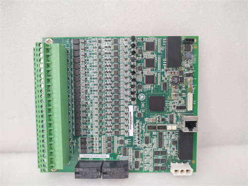
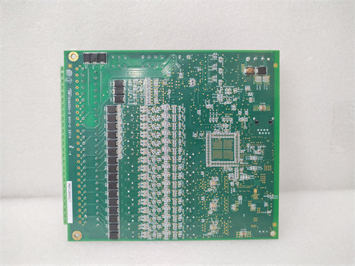
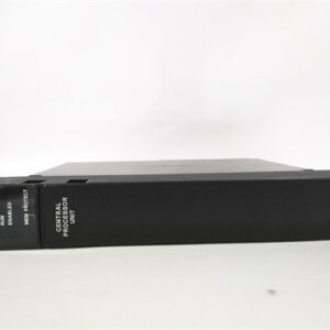
The GE DS200UDSAG1APR2 is a specific revision of a Display/Keyboard Interface Board (also referred to as an Excitation Board) used in the General Electric Mark V Speedtronic Turbine Control System and related excitation control systems (like the $\text{EX2000}$).
This part number is highly specific, where the suffix ‘PR2’ denotes a particular artwork and functional revision of the base board.
💡 Board Identification and Function
| Feature | Details |
| Full Part Number | DS200UDSAG1APR2 |
| Control Series | GE Mark V Speedtronic Turbine Control System ($\text{DS200}$ product series) |
| Functional Abbr. | UDSA (often stands for User Display/Keyboard Scanner Assembly) |
| Primary Function | Operator Interface (HMI): It facilitates local monitoring, diagnostics, and control input for the turbine’s excitation system. |
| Revision Level | ‘PR2’ denotes a specific, late functional and artwork revision of the board. The ‘A’ indicates the assembly type (e.g., normal assembly). |
Role in the Excitation System
Although the board’s main components are for display and input, it is vital to the turbine’s Excitation Control System. The excitation system’s core purpose is to provide regulated direct current ($\text{DC}$) to the generator’s field windings to control the output voltage.
The $\text{DS200UDSAG1APR2}$ allows a plant operator or technician to:
- Monitor critical parameters (e.g., generator voltage, field current, alarms).1
- Change control modes (e.g., Automatic Voltage Regulator (2$\text{AVR}$) to Manual).3
- View diagnostic and trip messages locally.
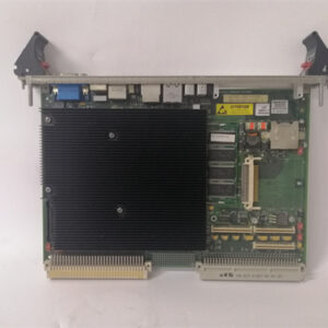
Key Hardware Components (Standard for UDSA Boards)
Like other $\text{DS200UDSA}$ revisions (like $\text{G1A}$ or $\text{G1ADE}$), the $\text{APR2}$ version includes the necessary physical components for the local interface:
- Microprocessor: Typically contains an 4$\text{80196}$ microprocessor for controlling board logic.5
- Displays: Features multiple (6$\text{21}$) 4-character displays and numerous (7$\text{32}$) LED status indicators for visual feedback.8
- Memory: Integrates EPROM modules to hold the control program and data.9
- Keypad Interface: Connects to the local keypad for operator input and control.10
- Connectivity: Includes communication circuitry (11$\text{RS-232C}$ interface) and a 12$\text{40}$-pin connector to communicate with the main controller modules in the Mark V panel.13
The $\text{APR2}$ designation indicates this is a later iteration, suggesting potential minor component changes, bug fixes, or hardware updates compared to earlier versions (like the $\text{G1A}$) to maintain compatibility or improve reliability within the legacy Mark V system.