+86 15340683922
 +86 15340683922
الوصف
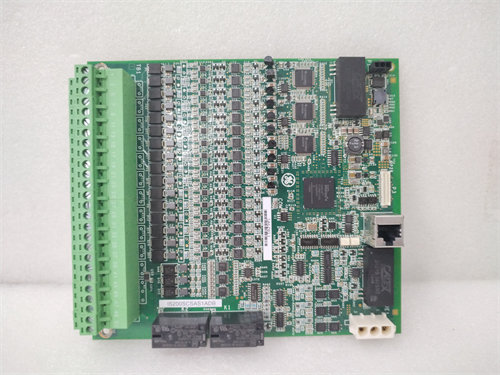
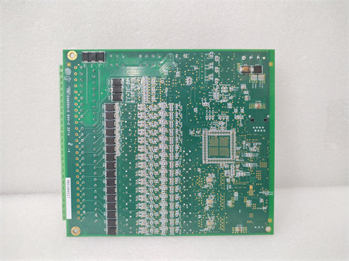
The GE DS200UPLAG1A LAN Power Supply Card is a key component within the General Electric Mark V Speedtronic Turbine Control System (and related systems like 1$\text{EX2000}$ Excitation Control).2
Its primary function is to provide stable, regulated power to the Local Area Network (3$\text{LAN}$) communication circuits and associated components within the control system cabinet.4
💡 Role and Function in Mark V System
The DS200UPLAG1A board (often referred to by its functional acronym UPLA) is essential for maintaining the communication backbone of the turbine control system.5
- Network Power: It supplies the necessary $\text{DC}$ power ($\text{+5 V}$, $\pm \text{24 V}$, etc.) to the LAN cards and other logic components that handle data transfer between the main controllers ($\text{R}$, $\text{S}$, $\text{T}$) and the system interfaces.
- System Communication: The reliable power it delivers is critical for the functioning of the internal Mark V communication networks, such as the $\text{DENET}$ (Data Exchange Network) and the $\text{StageLink}$ or $\text{PDH}$ (Plant Data Highway) which often use the ARCNET protocol. This network communication is vital for the Software-Implemented Fault Tolerance ($\text{SIFT}$) that the Mark V uses to perform 2-out-of-3 voting on critical control and protection parameters.
- Module Power: In certain configurations, it may also provide power for the $\text{Operator Interface}$ module.
⚙️ Technical Specifications (General UPLA Board)
The 6$\text{DS200UPLAG1A}$ is a member of the 7$\text{DS200}$ series of printed circuit boards.8 The trailing letter ‘$\text{A}$‘ indicates a specific revision level. While detailed manuals for legacy boards are scarce, general specifications for the $\text{UPLA}$ function include:
- Functional Acronym: 9$\text{UPLA}$ (LAN Power Supply Circuit)10
- System Series: 11$\text{Mark V}$ Speedtronic Turbine Control12
- Key Components:
- Switching power supply circuits for voltage regulation.13
- Connectors: Typically features 14$\text{26-pin}$ connectors for ribbon cable connections and an 15$\text{8-pin}$ connector.16
- Configuration: Includes a fuse, a reset button, and may have 17$\text{DIP}$ switches (up to 16) and jumpers (up to 17) for factory testing or site-specific configuration.18
- Best Practice: When replacing a 19$\text{DS200UPLAG1A}$ card, maintenance personnel must ensure that all 20$\text{DIP}$ switches and jumper settings on the replacement board are set exactly as they were on the original board to ensure proper system function and compatibility.21