+86 15340683922
 +86 15340683922
الوصف
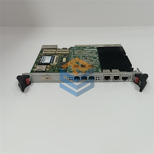
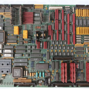
The GE DS200UPLAG1ABA LAN Power Supply Card is a printed circuit board (1$\text{PCB}$) used in the General Electric Mark V Speedtronic Turbine Control System.2
Its primary role, indicated by the functional acronym 3$\text{UPLA}$, is to provide stable and regulated power specifically for the Local Area Network (4$\text{LAN}$) communication components within the control panel.5
⚙️ Key Functionality and Application
The Mark V is a highly reliable, fault-tolerant control system, often employing Triple Modular Redundancy ($\text{TMR}$). The DS200UPLAG1ABA is crucial for supporting this architecture:
- LAN Power Supply: It ensures a clean power source for the communication circuitry, which is vital for the $\text{R}$, $\text{S}$, and $\text{T}$ controllers to exchange data and execute the necessary 2-out-of-3 voting logic.
- System Reliability: Stable power to the 6$\text{LAN}$ is non-negotiable for maintaining high-speed, reliable data transfer between the various controller cards and modules in the system.7
- Industrial Use: It’s designed for use in rugged industrial environments to control and manage gas, steam, or wind turbines.8
🔎 Technical Specifications and Components
The full part number, 9$\text{DS200UPLAG1ABA}$, denotes specific revisions to the board:10
| Segment | Description | Revision Detail |
| DS200 | Series | GE $\text{Mark V}$/Drive Control product line |
| UPLA | Functional Acronym | LAN Power Supply Circuit |
| G1 | Grouping | Design Group 1 |
| A | 1st Functional Revision | Revision A |
| B | 2nd Functional Revision | Revision B (indicates an update/improvement) |
| A | Artwork Revision | Revision A (PCB layout/coating) |
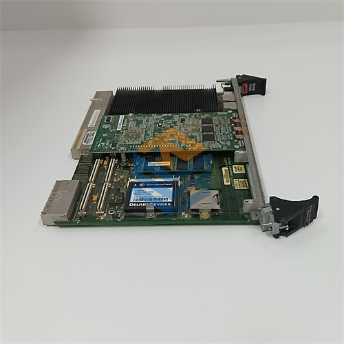
On-Board Hardware
The 11$\text{UPLA}$ board typically contains several physical components essential for its operation and configuration:12
- Connectors: A pair of 26-pin connectors and an 8-pin connector for power input, output, and ribbon cable connection to other modules.13
- Switches/Jumpers: Contains blocks of switches (often 14$2 \times 8$ switches) and jumpers that allow maintenance personnel to customize or configure the board’s behavior and settings for the specific turbine application.15
- Protection: Includes at least one fuse and a reset button.16
⚠️ Replacement Note
When replacing this board, it is essential to carefully document and match the configuration settings (jumpers and switches) of the faulty board to the replacement board to ensure the control system functions correctly.17