+86 15340683922
 +86 15340683922
الوصف
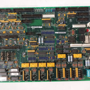
The GE DS200UPLAG1BDA LAN Power Supply Board is a circuit board used in the General Electric Mark V Speedtronic Turbine Control System and related industrial drive assemblies.1
Its core function (2$\text{UPLA}$) is to provide stable, regulated power to the system’s local area network (3$\text{LAN}$) communication components.4 This is crucial for the fault-tolerant operation of the Mark V system.
🔍 Part Number Breakdown and Function
The full part number 5$\text{DS200UPLAG1BDA}$ contains key information about the board’s design and revision:6
| Segment | Meaning | Detail |
| DS200 | Series Tag | Identifies it as a board for the $\text{GE Mark V}$ Turbine Control System. |
| UPLA | Functional Acronym | Stands for LAN Power Supply Circuit. |
| G1 | Grouping Tag | Design Group 1. |
| B | Functional Revision 1 | The second major functional version of the hardware. |
| D | Functional Revision 2 | A subsequent minor functional or firmware revision. |
| A | Artwork Revision | The first artwork/physical layout revision. |
Role in Turbine Control
The $\text{Mark V}$ system is a Triple Modular Redundant ($\text{TMR}$) control system that relies on high-speed network communication (like $\text{ARCNET}$ or $\text{DLAN}$) to allow its three processors ($\text{R}$, $\text{S}$, and $\text{T}$) to vote on commands. The 7$\text{DS200UPLAG1BDA}$ ensures the communication circuitry remains energized with clean, consistent power, which is essential for maintaining the system’s reliability and its ability to prevent spurious trips.8
🛠️ Hardware and Replacement Considerations
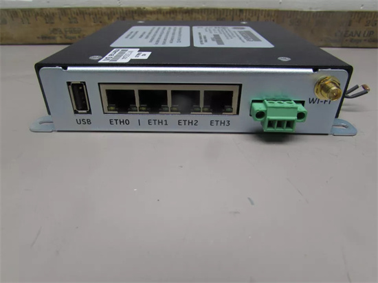
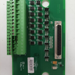
- Components: The 9$\text{UPLA}$ board typically includes two 26-pin ribbon cable connectors for control signals, a fuse, a reset button, a toggle switch, and critical configuration settings.10
- Configuration: The board is populated with several jumpers (often 17) and $\text{DIP}$ switches (often 16) that must be set precisely for the specific turbine or drive application.
- Replacement Best Practice: When replacing a $\text{DS200UPLAG1BDA}$ board, the jumpers and switches on the new (or repaired) board MUST be set to exactly match the configuration of the old board before installation. Failure to do so will likely result in a system fault or improper operation.