+86 15340683922
 +86 15340683922
الوصف
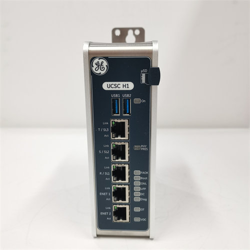
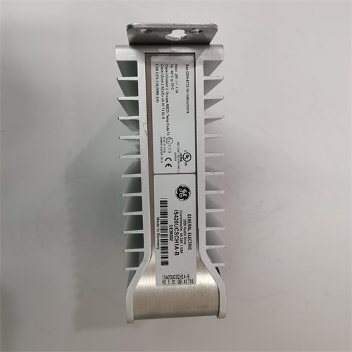
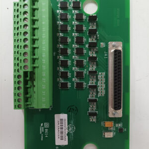
The GE DS200UPSAG1A is a specialized circuit board known as a Power Supply Board or UC2000 Power Supply Assembly (1$\text{UPSA}$).2 It is a vital component of the GE EX2000 Excitation Control System and is used in conjunction with the Mark V Speedtronic Turbine Control System.3
⚡ Core Function and Role
The primary purpose of the 4$\text{DS200UPSAG1A}$ is to provide stable and reliable low-voltage 5$\text{DC}$ power to the logic and control circuitry within the EX2000 excitation system.6
- Power Conversion: It is typically a two-stage offline switching power supply (rated around 7$\text{100 W}$) that converts a higher 8$\text{AC}$ or 9$\text{DC}$ input voltage (from the station power or battery) into the multiple, regulated 10$\text{DC}$ voltages (e.g., 11$\text{+5 V}$, 12$\pm \text{15 V}$, 13$\pm \text{24 V}$) required by the digital control boards.14
- System Integrity: By providing clean power, it ensures the continuous and accurate operation of the microprocessors and control logic responsible for regulating the generator’s field current and maintaining stable terminal voltage.15
- Application: It is integral to the 16$\text{EX2000}$ series, which controls the excitation system for large industrial generators driven by gas or steam turbines.17
🛠️ Key Technical Features
The 18$\text{DS200UPSAG1A}$ board is designed for industrial environments and includes several features for protection and diagnostics:19
- Processor & Memory: It contains the necessary circuits to manage the power supply process.
- Fuses: It is protected by multiple fuses (e.g., three or four), which are designed to blow and shut down the circuit in the event of an over-voltage or over-current condition.20 (Note: These fuses must only be replaced with the exact specified rating).21
- Status Indicator: Includes a 22$\text{PS OK}$ 23$\text{LED}$ (24$\text{DS1}$) that illuminates green when the power supply is on and all output voltages are within specified limits.25
- Controls:
- Reset Button ($\text{SW2}$): Allows the operator to reset the board without removing the input power.26
- Potentiometer ($\text{RV1}$): A factory-set component used for fine-tuning the voltage output (e.g., adjusting the 27$\text{+5 V}$ output at test point 28$\text{TP5}$).29
- Connectors: Features multiple 30$\text{9-pin}$ connectors (31$\text{2PLA}$, 32$\text{2PLB}$, 33$\text{2PLC}$) for connecting to the 34$\text{EX2000}$‘s backplane and other boards.35
Safety Warning: Like all power supply boards, the $\text{DS200UPSAG1A}$ contains high-voltage capacitors that can store a lethal electrical charge even after power is removed. Maintenance procedures explicitly require waiting a specified period (e.g., 30 seconds) after power removal before handling the board.36