+86 15340683922
 +86 15340683922
الوصف
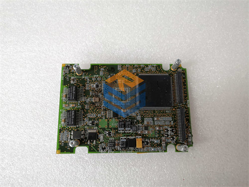
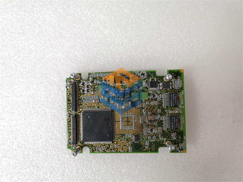
The GE DS200UPSAG1ADB Power Supply Board is a circuit card that functions as the Power Supply Assembly (1$\text{UPSA}$) for critical components within the General Electric control environment.2
It is primarily used in the $\text{EX2000}$ Excitation Control System and is associated with the Mark V Speedtronic Turbine Control System.
⚡ Core Function and Role
The 3$\text{DS200UPSAG1ADB}$ board is vital for the reliable operation of the excitation and turbine control modules:4
- Power Conversion: Its main function is to convert the higher $\text{AC}$ or $\text{DC}$ input voltage (from the station power or battery) into the stable, regulated low-voltage $\text{DC}$ power ($\text{+5 V}$, $\pm \text{15 V}$, $\pm \text{24 V}$, etc.) required by the digital logic boards, microprocessors, and control circuits of the $\text{EX2000}$ system.
- System Integrity: By providing clean and consistent power, it ensures the continuous and accurate execution of the excitation control algorithms, which regulate the generator’s field current and output voltage.
- Design: It is typically a switching power supply rated around 5$\text{100 W}$ and is built robustly for the demanding industrial environment of power generation facilities.6
🔍 Part Number and Technical Features
The part number $\text{DS200UPSAG1ADB}$ indicates a specific revision of the base $\text{UPSA}$ board:
| Segment | Meaning | Detail for DS200UPSAG1ADB |
| DS200 | Series Tag | $\text{GE Mark V}$ / Drive Control Product Line |
| UPSA | Functional Acronym | UC2000 Power Supply Assembly |
| G1 | Grouping Tag | Design Group 1 |
| A | 1st Functional Revision | Revision A |
| D | 2nd Functional Revision | Revision $\text{D}$ (Indicates a minor functional or engineering change) |
| B | Artwork Revision | Revision $\text{B}$ (Indicates a change in the physical layout/coating) |
Common Features
Like other $\text{UPSA}$ boards, the $\text{DS200UPSAG1ADB}$ includes:
- Protection: Multiple fuses for over-current protection.7
- Diagnostics: A PS OK $\text{LED}$ (Power Supply OK) to indicate healthy output voltages.
- Controls: A Reset Button ($\text{SW2}$) and often a potentiometer ($\text{RV1}$) for factory or maintenance voltage tuning.
- Connectivity: Multiple 8$\text{9-pin}$ connectors for power and signal distribution within the cabinet.9
⚠️ Safety Warning: As a power supply board, this component contains capacitors designed to store high-voltage current.10 Extreme caution must be used. Always follow manufacturer guidelines and wait at least 11$\text{30 seconds}$ after disconnecting power before handling the board to allow the capacitors to fully discharge.12