+86 15340683922
 +86 15340683922
الوصف
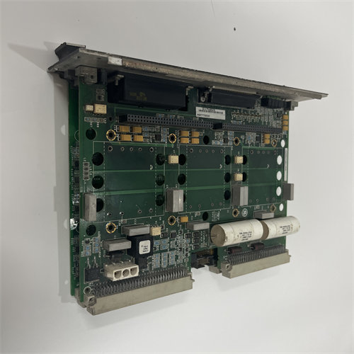
The GE DS200UPSAPG1A Power Supply Board is a highly specific circuit board integral to the General Electric Mark V Speedtronic Turbine Control System and the associated EX2000 Excitation Control System.1
The functional acronym UPSA (or often 2$\text{UPSAP}$) stands for UC2000 Power Supply Assembly.3
⚡ Core Function and Application
The primary role of the DS200UPSAPG1A is to serve as the dedicated power supply for the logic and control circuits within the control module where it is installed.
- Power Conversion: It takes the incoming station $\text{AC}$ or $\text{DC}$ control power and converts it into the precise, regulated low-voltage $\text{DC}$ power ($\text{+5 V}$, $\pm \text{15 V}$, $\pm \text{24 V}$, etc.) required by the digital control boards (processors, I/O, etc.).
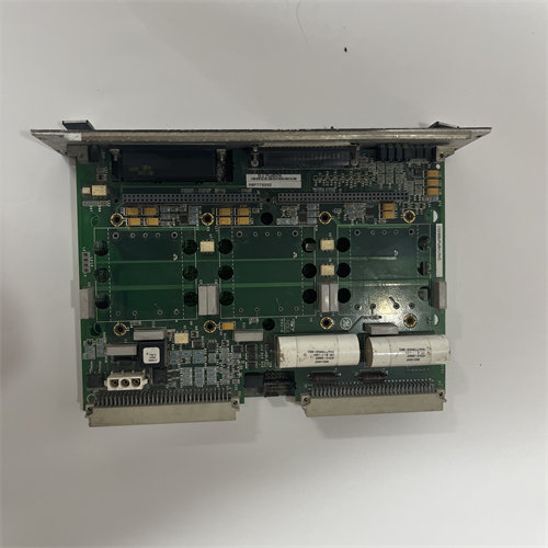
- System Integrity: By providing clean and consistent power, it ensures the continuous and accurate operation of the critical control algorithms and microprocessors that manage the turbine’s speed, load, and the generator’s excitation control (regulating voltage and reactive power).4
- Location: It is placed within the Mark V panel, often in the 5$\text{EX2000}$ portion of the system, which handles the generator’s field excitation.6
🔍 Part Number and Technical Features
The $\text{DS200UPSAPG1A}$ is a specialized version of the $\text{UPSA}$ board, with the $\text{P}$ in the acronym likely denoting a specific package, placement, or feature related to the $\text{EX2000}$ system.
Key Hardware Features
- Reset Button: Includes a reset button (7$\text{SW2}$) to restart board processing without removing input power, useful for clearing momentary faults.8
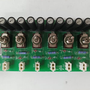
- Fuses: Protected by multiple fuses (typically three) to safeguard components from overvoltage or overcurrent conditions.9
- Status $\text{LED}$: Features at least one 10$\text{LED}$ (e.g., “PS OK”) to visually indicate that the board is powered and output voltages are within tolerance.11
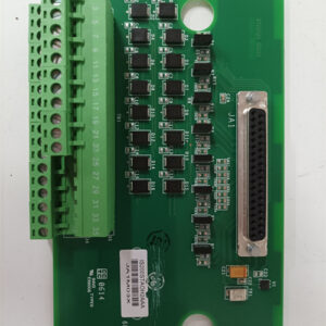
- Connectors: Populated with several connectors, typically 9-pin connectors, for distributing power and connecting to the backplane or adjacent boards.12
- Toggle Switch: This board often includes a toggle switch (13$\text{CHAS1}$) marked 14$\text{ON/OFF}$ to manually disable or enable specific board functions.15
- Test Points: Multiple test points (e.g., 16$\text{AC1}$, 17$\text{AC2}$, 18$\text{D COM}$, 19$\text{C COM}$) are available for authorized servicers to measure voltages and diagnose component-level issues.20
The final ‘21$\text{A}$‘ in the part number indicates a specific functional product revision that sought to improve the basic performance or functionality of the original design.22
⚠️ Safety Warning: As a power supply board, this component contains capacitors that can store a potentially lethal electrical charge even after power has been removed. Always follow safety procedures and allow sufficient discharge time before attempting to handle or service this board.