+86 15340683922
 +86 15340683922
الوصف
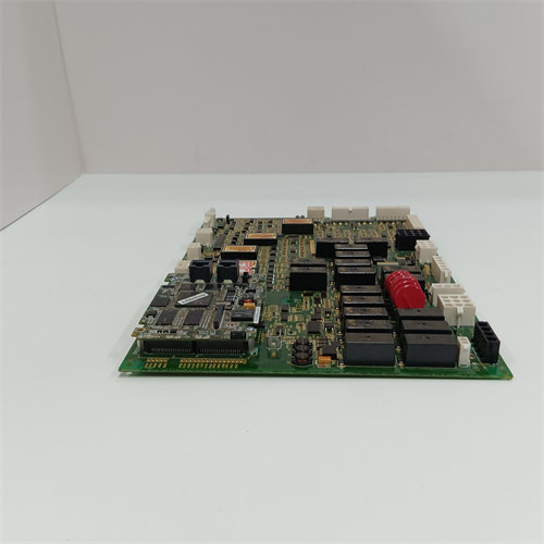
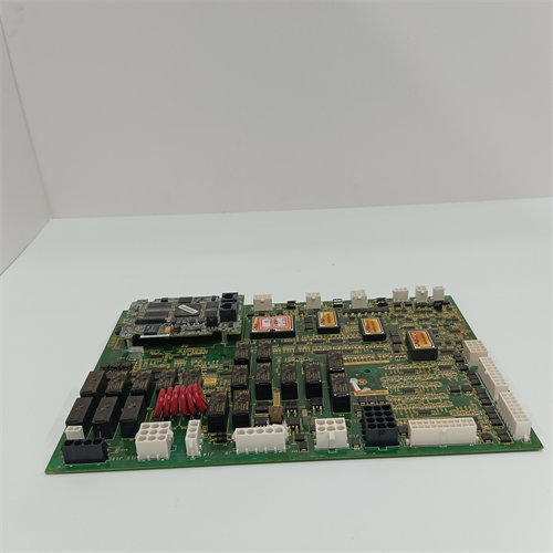
The GE DS200VPBLG1ACC is a VME Backplane Board (VPBL) primarily used in General Electric’s control systems, including the Mark V Speedtronic Turbine Control System and the LCI (Load Commutated Inverter) Drive Systems.
This board serves as the structural and electrical backbone for a specific card cage within the control panel, allowing various processor and I/O modules to communicate and receive power.
🏗️ Key Function and Structure
The VME Backplane is the critical infrastructure that connects the major control cards within a rack assembly:
- Communication Bus: It provides the VME bus architecture, which is the data highway for the installed circuit boards. This allows high-speed communication between the main Digital Signal Processor Control ($\text{DSPC}$) board and its associated I/O and Gating cards.
- Power Distribution: The board is a multi-layer design that is engineered to keep the digital and analog power planes separate. It includes power distribution and bypass capacitors at each slot to ensure stable and clean power delivery to every connected module.
- Card Support: The backplane is typically divided into sections ($\text{J2}$ and $\text{J3}$) to support various modules:
- $\text{J2}$ Section: Supports the DSPC Board (Digital Signal Processor Control), I/O Extenders, and up to three FCGD Boards (Gating and LCI Control Boards).
- $\text{J3}$ Section: Used for external connections (connectors not available on the board fronts), including connections for current transformers ($\text{CT}$), burden resistors, and the power supply connection.
🔍 Technical Features
The $\text{DS200VPBLG1ACC}$ is a high-performance board with diagnostic and connection features:
- Tachometer Settings: It includes configurable settings, typically via jumpers and a terminal block, for receiving and conditioning tachometer signals (turbine speed feedback) before they are sent to the CPU.
- Diagnostic Tools: Features numerous spring-loop test points (often 60 or more) that allow technicians to safely access and monitor analog and digital signals for diagnostics.
- Connectors: Includes a diagnostics connector (e.g., a 26-pin discrete cable connector) for system testing and an exciter connection (e.g., a 34-pin ribbon connector) for external exciter signals.
- Power Integrity: The board features ten power bugs that are crucial for efficient and stable power distribution to all connected modules.
Part Number Note
The $\text{DS200VPBLG1ACC}$ part number indicates the $\text{ACC}$ revision level, which specifies the particular version of the hardware and firmware/artwork for the base $\text{VPBL}$ design.