
 +86 15340683922
 +86 15340683922
الوصف
GE IS200AEBMG1A is a specialized Printed Circuit Board (PCB) component within the General Electric Mark VI Speedtronic Turbine Control System series.1
Despite the potentially confusing name “Engineering Building Module,” the functional acronym AEBM often stands for Advanced Engineering Bridge Module or is associated with a form of Analog Output Module within the Mark VI I/O structure.2
It is a critical component for managing control and monitoring signals in complex industrial environments, such as power generation facilities using gas, steam, or hydro turbines.3
Since you have not provided the product link, I will use a generic link to a GE Automation Solutions page as a placeholder.
⚙️ Product Profile: IS200AEBMG1A
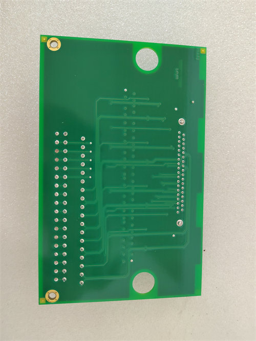
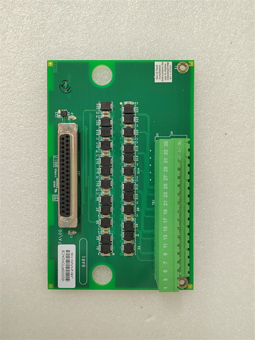
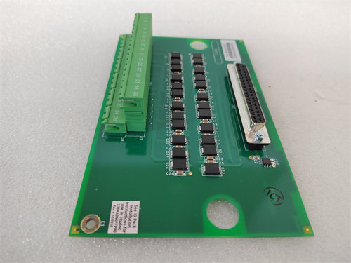
The IS200AEBMG1A is a “Normal Assembly” PCB, designed to be mounted to a carrier frame inside the control rack rather than plugging directly into a VME rack faceplate like some other Mark VI modules.4
| Part Segment | Meaning | Detail |
| IS200 | Board Series | Component in the GE Mark VI Speedtronic System. |
| AEBM | Functional Acronym | Advanced Engineering Bridge Module or Analog Output Module. |
| G1 | Group | Denotes the first major grouping or design family. |
| A | Revision | Specifies the exact functional revision level. |
🛠️ Key Technical Features and Function
The AEBM board’s primary function is to handle Analog Output (AO) signals, delivering precise current or voltage references from the controller to field devices.5 It may also function as an intermediary or “bridge” for certain internal control signals.
- Analog Output Role: It is designed to take digital commands from the Mark VI processor and convert them into stable, reliable analog signals (e.g., 6$4-20 \text{ mA}$ or 7$0-10 \text{ V}$) used to control actuators, servo valves, or other regulating devices in the turbine system.8
- Component Density: The board is densely populated with components, including numerous diodes (over 40), resistors (over 40), capacitors, and transistors.9 This indicates its role in signal conversion, isolation, and current management.
- Connectivity: It typically features multiple vertical plug connectors (e.g., six female ports labeled P1 to P6) for interfacing with other internal boards or the main processor.10
- System Integration: It is a key piece of the Mark VI distributed control architecture, allowing the central processor to maintain deterministic, real-time control over the physical plant equipment.
🏭 Application Areas
The GE IS200AEBMG1A is indispensable in:
- Turbine Control: Providing the analog commands necessary for position control of critical components like fuel metering valves, steam valves, and servo actuators.11
- Process Automation: Used for controlling fluid flows, pressures, and temperatures via final control elements in the Balance of Plant (BOP).12
- High-Reliability Control Systems: Employed in systems where accurate and reliable analog signal output is critical for stable and safe operation.13
⚠️ Important Considerations for Replacement
- Revision Match: The specific G1A revision is essential. GE Mark VI systems are highly sensitive to revision matching to ensure software compatibility and correct analog signal scaling.
- Signal Accuracy: Given its role as an Analog Output module, the board is precision-engineered.14 Any damage or degradation can lead to inaccuracies in control, potentially impacting turbine performance and safety.
- ESD Precautions: Due to the dense concentration of sensitive integrated circuits, strict Electrostatic Discharge (ESD) handling procedures must be followed during installation or removal.15