+86 15340683922
 +86 15340683922
الوصف
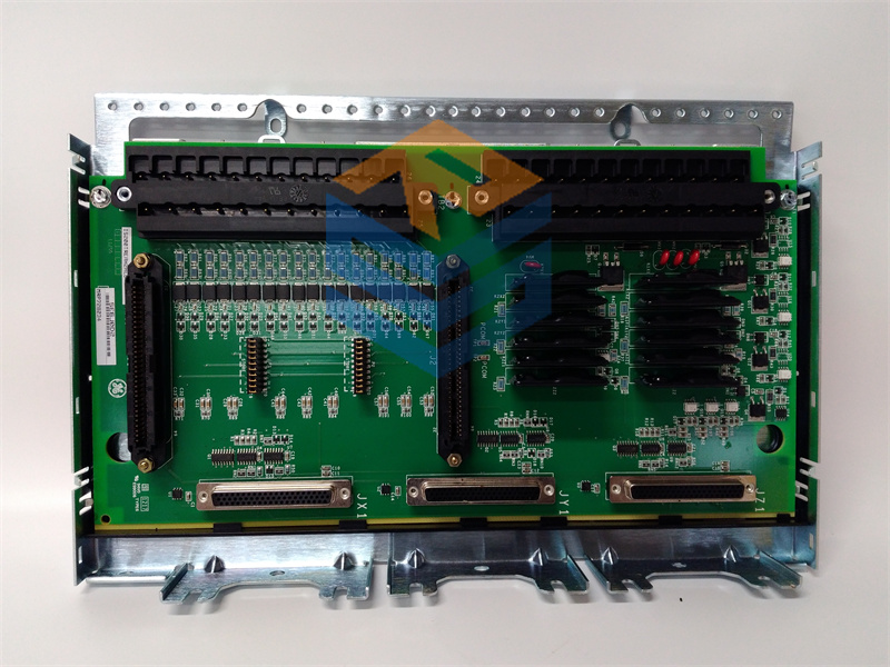
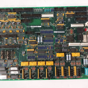
GE IS200ATBAG1A is a specialized Printed Circuit Board (PCB) component manufactured by General Electric for their high-reliability control platforms, primarily the Mark VI Speedtronic Turbine Control System and Innovation Series Drives.
Its functional acronym, ATBA, stands for Application Input/Output (I/O) Terminal Board. It is not a processor, but a vital interface component used to connect customer field wiring to the system’s internal backplane.
⚙️ Product Profile: IS200ATBAG1A
The IS200ATBAG1A is classified as a “Normal Assembly” board (IS200 series) and is typically mounted on a DIN rail inside the control cabinet. It provides a secure, organized interface for customer connections, particularly to GE’s Innovation Series drives.
| Parameter | Specification/Detail |
| Functional Acronym | ATBA (Application I/O Terminal Board) |
| System Family | GE Mark VI Speedtronic / Innovation Series Drives. |
| Primary Function | Provides the terminal block interface between customer field wiring and the signals on the Control Assembly Backplane Board (CABP). |
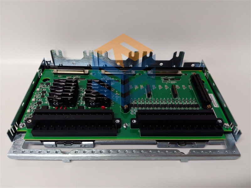
| Connectivity | Features a single terminal block with 60 positions (two terminal strips) for field wiring connections. |
| Backplane Interface | Connects to the CABP via two vertical male pin connectors: J6 (36-pin) and J7 (24-pin). |
| Wiring Capacity | Terminals accept either one stranded wire or two stranded wires. |
| Adjustable Hardware | None. The board does not have fuses or adjustable jumpers, as the hardware is set to factory specifications. |
| Revision | G1A—Specifies the specific Group (G1) and Revision (A). Compatibility with the system firmware depends heavily on this code. |
| Manual Reference | Documented in GE Instruction Manual GEI-100284A (or similar revision). |
🛠️ Function and I/O Assignment
The ATBA board’s primary role is to aggregate the diverse I/O signals from the CABP backplane and present them to the customer in an accessible terminal block format.
The terminal block provides connections for a wide range of signals, including:
- Digital Outputs (DO): Often connected to relays for switching.
- Analog Outputs (AO): For sending control signals (e.g., ) to actuators.
- Digital Inputs (DI): For monitoring limit switches, protective signals, and fault strings.
- Tachometer: Inputs for speed measurement.
- Analog Inputs (AI): Such as MA Pilot and feedback signals.
Note: Specific terminal assignments for signals like fault strings, relays (, , ), and I/O channels are detailed in the GEI-100284A manual, organized by the () and () connector signals.
⚠️ Important Considerations for Replacement
- Revision Match: The G1A revision is critical. Different revisions of the board (e.g., vs. ) have different pin reassignments for connectors and . You must ensure the replacement board matches the existing one to avoid incorrect wiring and system damage.
- Safety: The board interfaces with circuits rated for up to . Always ensure the drive/control cabinet is fully de-energized and test circuits for high voltage before handling the board.
- ESD Precautions: Handle the board as a static-sensitive component, keeping it in anti-static packaging until installation.