+86 15340683922
 +86 15340683922
الوصف
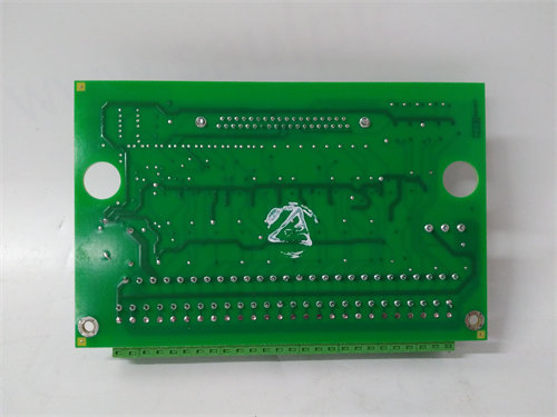
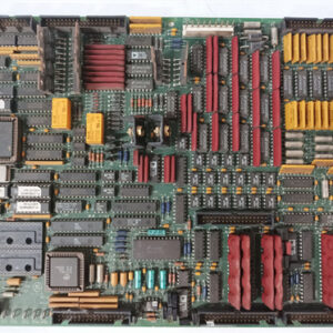
The GE IS200ATBAG1AAA is a specialized Printed Circuit Board (PCB) component, specifically an Application Input/Output (I/O) Terminal Board (ATBA), manufactured by General Electric for the Mark VI Speedtronic Turbine Control System and its associated Innovation Series Drive assemblies.
This board’s primary role is not processing, but serving as the crucial physical interface for connecting external, customer-supplied field wiring to the system’s internal I/O signals.
⚙️ Product Profile: IS200ATBAG1AAA
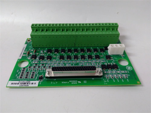
The IS200ATBAG1AAA is a “Normal Assembly” board (IS200 series) that is typically mounted on a DIN rail inside the control cabinet. It is a passive interface with no adjustable hardware.
| Parameter | Specification/Detail |
| Functional Acronym | ATBA (Application I/O Terminal Board) |
| System Family | GE Mark VI Speedtronic / Innovation Series Drives. |
| Primary Function | Provides a 60-position terminal block for all field wiring to connect to the internal signals carried on the Control Assembly Backplane Board (CABP). |
| Connectivity | Features a single terminal block with two terminal strips (60 total positions). Connects to the CABP via two vertical male pin connectors: J6 (36-pin) and J7 (24-pin). |
| Wiring Capacity | Accepts one stranded $\text{\#12 AWG}$ wire or two $\text{\#16 AWG}$ stranded wires per terminal. |
| Revision | G1AAA—Designates a specific revision belonging to the G1AA revision group. The multiple ‘A’s are critical for pin assignment compatibility. |
| Key Signals Handled | Digital Outputs (DO), Analog Outputs (AO), Digital Inputs (DI), Analog Inputs (AI), and tachometer signals. |
| Manual Reference | Documented in GE Instruction Manual GEI-100284A (or similar revision). |
🛠️ Function and Terminal Assignments
The ATBA board translates the high-density signals from the Control Assembly Backplane Board ($\text{CABP}$) into easily accessible screw-terminal points for technicians:
- Signal Aggregation: All I/O signals required for the drive/turbine application, which originate from internal I/O modules plugged into the backplane, are terminated onto this single board.
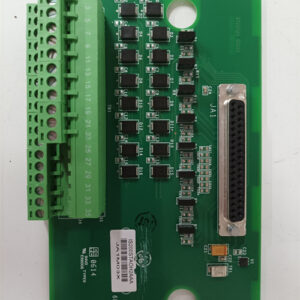
- Pin Assignments: The board is rigidly divided:
- Terminals 1-36 connect to the J6 backplane connector.
- Terminals 37-60 connect to the J7 backplane connector.
- Voltage Ratings: Connector J6 pins are typically rated for a maximum of $225 \text{ V}$ and $1 \text{ A}$, while J7 connections are rated lower, typically $50 \text{ V}$ and $1 \text{ A}$. Certain digital output relay connections on J6 (e.g., $\text{RLY1COM}$, $\text{RLY1NO}$) also handle the higher voltage.
⚠️ Important Considerations for Replacement
- Revision Match is Essential: The G1AAA version belongs to the $\text{G1AA}$ revision group, which has specific pin assignments for connectors $\text{J6}$ and $\text{J7}$. You must match the revision exactly (or use a GE-approved substitute) because the pin assignments for signals like $\text{SSRN}$ (a ground return) can change between revision groups ($\text{G1AA}$ vs. $\text{G1AB}$). Using an incompatible board will lead to miswired signals and potential equipment damage.
- Safety: Always de-energize and test for the presence of lethal voltages (up to $225 \text{ V}$) on the terminals before handling the board.
This video provides a tutorial on using the Mark VIe’s software interface, which is the platform used to configure and monitor the signals carried by the IS200ATBAG1AAA