+86 15340683922
 +86 15340683922
الوصف
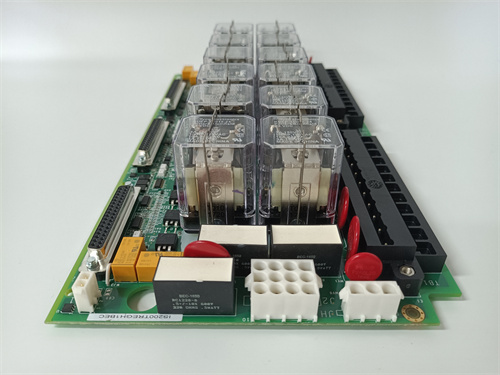
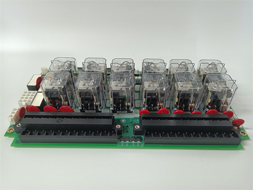
GE IS200ATBAG1BAA1 is a specialized Printed Circuit Board (PCB) component known as an Application Input/Output (I/O) Terminal Board (1$\text{ATBA}$).2 It is a critical, passive interface card used in General Electric’s Mark VI Speedtronic Turbine Control System and its associated Innovation Series Drive assemblies.3
It does not perform processing; its sole purpose is to serve as the secure physical interface between external customer field wiring and the system’s internal I/O signals.
⚙️ Product Profile and Function
The IS200ATBAG1BAA1 is an IS200 series “Normal Assembly” board, typically mounted on a DIN rail inside the control cabinet.4
| Parameter | Detail |
| Functional Acronym | ATBA (Application I/O Terminal Board) |
| Primary Function | Provides a 60-position screw terminal block for connecting customer field wiring (e.g., sensors, relays, actuators) to the internal signals of the main control backplane. |
| System Compatibility | GE Mark VI Speedtronic Turbine Control and Innovation Series Drives. |
| Connectivity | Connects to the Control Assembly Backplane Board ($\text{CABP}$) via two vertical male pin connectors: J6 ($\text{36-pin}$) and J7 ($\text{25-pin}$). |
| I/O Variety | The $\text{60 terminals}$ are assigned to various signals, including Digital Inputs ($\text{DI}$), Analog Inputs ($\text{AI}$), Analog Outputs ($\text{AO}$), Digital Outputs ($\text{DO}$) via relay contacts, Tachometer inputs, and fault strings. |
| Revision | G1BAA1—This complex suffix specifies the exact hardware and artwork configuration, which is vital for pinout compatibility. |
🛠️ Key Technical Features
- Terminal Block: Features one single terminal block with 60 positions (two rows of 30) labeled for easy identification of signal types.5
- Non-Configurable: The board is fixed hardware with no user-adjustable components, such as fuses or jumpers, as the hardware is set to factory specifications.6
- Voltage Ratings: The two backplane connectors have different voltage ratings:7
- J7 Connections: Generally rated for 8$50 \text{ VDC}$ maximum at 9$\text{1 A}$.10
- J6 Connections: Generally rated for up to 11$225 \text{ VDC}$ at 12$\text{1 A}$, especially for the relay contact terminals (13$\text{RLY1COM}$, 14$\text{RLY1NC}$, etc.)15
- Safety Features: The board often includes a cable shield border to protect and contain cables.16
⚠️ Important Considerations for Replacement
- Revision Match is Essential: The G1BAA1 revision is highly specific. Different revisions of the 17$\text{ATBA}$ board have reassigned pins on connectors J6 and J7.18 You must replace the board with an exact match or an approved, documented substitute to prevent miswiring critical I/O signals and causing system damage.
- Safety: Before handling or replacing this board, it is imperative to fully de-energize the drive/control cabinet and test the circuits, especially those on the J6 side, to ensure that no high voltages (19$\text{up to 225 VDC}$) are present.20