+86 15340683922
 +86 15340683922
الوصف
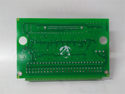
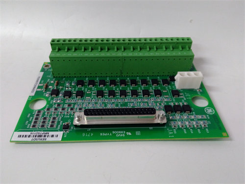
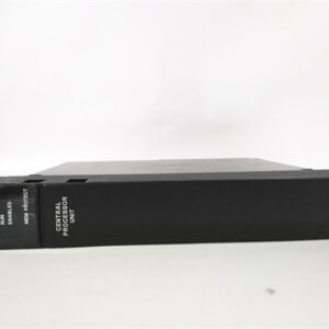
The GE IS200BAIAH1BDC is a highly specific Printed Circuit Board (PCB) known as the Bridge Application Interface Board (). It is an essential component in General Electric’s Mark VI Speedtronic Turbine Control System and its associated Innovation Series Drive assemblies.
Its primary function is to serve as a critical communication, isolation, and signal conditioning bridge between the main Digital Signal Processor ( board) and the external field wiring and user interfaces.
⚙️ Key Technical Features and Function
The board is a VME-style card designed for vertical installation into a dedicated slot within the control rack. The suffix H1BDC denotes a specific hardware and firmware revision, which is vital for system compatibility.
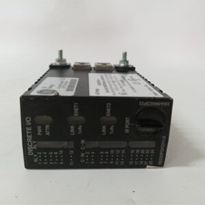
- Signal Isolation and Earth Ground Reference: The board provides electrical isolation and an earth-ground reference for signal inputs coming from external terminal boards. This is crucial for protecting the sensitive low-voltage control electronics from electrical noise and voltage discrepancies in the high-voltage industrial environment.
- Communication Interface: It includes an RS-232C I/O interface, which provides the communication path between the main processor () and the drive system’s keypad and PC connections for diagnostics and configuration.
- Digital-to-Analog Conversion: It converts digital inputs received from the board into analog outputs. These outputs are used for purposes like driving panel meters or providing general analog feedback (channels A and B).
- Configurable Analog Inputs: The board supports two bipolar () analog input channels. It contains five jumpers that allow a technician to configure the input to accept either a voltage input () or a (current input) signal.
- Discrete I/O: It features three Form C relays for discrete output switching and includes several isolated discrete logic inputs.
- Safety Warning: The board typically has a warning label on its faceplate stating, “Install in Slot 1 only,” as placing it in an incorrect VME rack slot will cause damage.
- Firmware: It has an onboard EEPROM with factory-preloaded firmware that should never be reprogrammed or removed in the field.
⚠️ Important Considerations for Replacement
- Revision Match is Crucial: The suffix H1BDC must be matched exactly when sourcing a replacement. Given the board’s role in signal isolation, scaling, and communication protocol, an incorrect revision risks communication failures, improper signal interpretation, and damage to the control system components.
- ESD Precautions: This board is densely populated with sensitive integrated circuits and must be handled using strict Electrostatic Discharge () procedures.