
 +86 15340683922
 +86 15340683922
الوصف
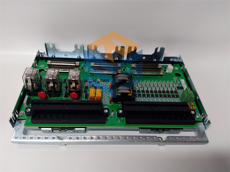
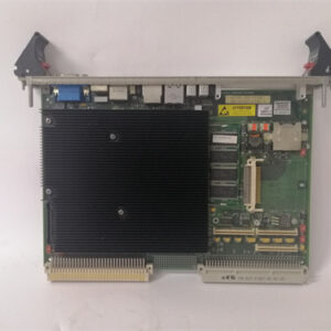
The GE IS200BPIBG1A is a highly specialized Printed Circuit Board (PCB) known as the Bridge Personality Interface Board (1$\text{BPIB}$) or Phase Logic Module (2$\text{PLIM}$).3 It is a critical component in General Electric’s Mark VI Speedtronic Turbine Control System, particularly when integrated with the EX2100 Excitation Control System or Innovation Series Drives.4
Its core function is to provide the logic and signal conditioning necessary to interface the main control system with the high-voltage power semiconductor drivers (like IGBTs) in a converter or exciter bridge.5
⚙️ Core Function: Phase Logic & Drive Personality
The $\text{BPIB}$ acts as a “personality” interface because it is specifically configured to match the phase logic, fault handling, and signal requirements of the external power bridge components.
- Signal Conditioning and Isolation: It receives logic control signals from the main VME rack (via the P1 connector) and conditions them before sending them to the Gate Driver and Shunt Feedback Boards.6 The board uses double optocoupled logic signals and galvanic separation to ensure high noise immunity and signal integrity between the control and power sides.7
- Fault Capture and Reporting: A primary function is to capture and process faults reported by the connected Gate Driver boards.8 Some faults are handled locally on the 9$\text{BPIB}$ via onboard logic (often implemented in EPLDs—Electronically Programmable Logic Devices), while others are latched and reported back to the main controller.10
- Fault functions include driver shutdown and fault latch-on for each phase.11
- VCO Feedback Processing: It processes signals from isolated Voltage Controlled Oscillator (12$\text{VCO}$) feedback circuits.13 These circuits monitor critical bridge parameters like the DC Link voltage and phase-to-phase output voltages (14$\text{VAB}$ and 15$\text{VBC}$).16
- In parallel bridge configurations, the 17$\text{BPIB}$ conditions and averages the two 18$\text{VCO}$ signals per phase, often tripping the system if an imbalance exceeds 19$\text{10%}$.20
- Driver Control Capacity: The board can manage the control signals for up to three Gate Driver Boards in a single bridge configuration, or up to six Gate Driver Boards when wired in a parallel bridge configuration.21
🛠️ Technical Details and Installation
The IS200BPIBG1A is a VME-style board designed for installation in a specific slot within the Mark VI control rack.22
| Parameter | Detail |
| Functional Acronym | BPIB (Bridge Personality Interface Board) or PLIM (Phase Logic Interface Module) |
| System Family | GE Mark VI Speedtronic / EX2100 Excitation Control. |
| Mounting | VME Rack (Plugs in via the P1 connector). |
| Onboard Logic | Uses EPLDs (Electronically Programmable Logic Devices) for phase control and fault processing. |
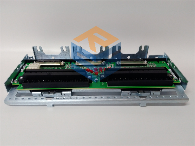
| I/O | Six plug connectors for Gate Driver Boards; Five stab-on connectors for phase sensing and DC-link signals. |
| Power Sources | Requires isolated $\text{5 VDC}$ control power and $\text{17.7 VAC}$ for internal isolated power supplies. |
| Manual Reference | Documented in GE Instruction Manual GEI-100266. |
⚠️ Important Considerations for Replacement
- Revision Match is Essential: The G1A suffix must be matched exactly when replacing the board. Since the $\text{BPIB}$ handles phase logic and critical fault handling, installing an incompatible revision can lead to incorrect timing, failed protection logic, or system malfunction.
- Slot Restriction: Though the specific slot is not uniformly published, 23$\text{BPI}$ boards are often restricted to a specific VME slot (like Slot 6 for the 24$\text{BPIA}$) to ensure proper backplane connection.25 Always confirm the correct slot before installation.