+86 15340683922
 +86 15340683922
الوصف
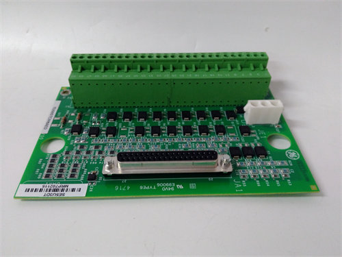
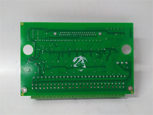
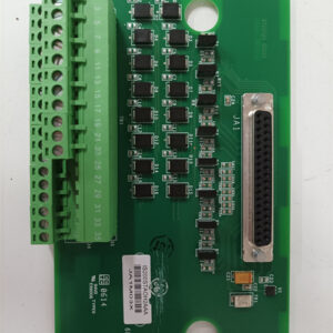
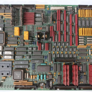
The GE IS200BPIRG1AAA is a highly specific Printed Circuit Board (PCB) known as the Bridge Interface Board (1$\text{BPIR}$) or Digital Interface Board.2 It is a critical communications component within General Electric’s Mark VI Speedtronic Turbine Control System, particularly in systems integrated with the Innovation Series Medium Voltage – GP, Type H Drives.3
Its primary role is to serve as a digital bus interface for internal communication within the drive control rack.4
⚙️ Core Functionality
The 5$\text{BPIR}$ board acts as a signal conditioning and conversion layer, providing the necessary digital bus interface for the control architecture of the drive.6
- Digital Bus Interface: The 7$\text{BPIR}$ functions as a 8$15 \text{ V}$ to 9$5 \text{ V}$ interface for the digital bus.10 This is necessary because different boards in the control rack operate at different voltage logic levels, and the $\text{BPIR}$ ensures proper signal transmission between them.
- Interfacing Two Key Boards: Its main job is to provide the digital bus interface between two other critical drive control boards:11
- The 12$\text{BICR}$ (Bridge Interface Card).13
- The 14$\text{FOHB}$ (Fiber Optic Hub Board).15
- Signal Transport: It passes essential operational signals, such as phase reference analog signals (16$\text{REFA}$, 17$\text{REFB}$, 18$\text{REFC}$) and bridge cell temperature data, between these connected boards.19
🛠️ Technical Details and Installation
The IS200BPIRG1AAA is a VME-style board designed for mounting within the Innovation Series board rack.20 The extended suffix G1AAA denotes a specific and mandatory hardware/firmware revision.
| Parameter | Detail |
| Functional Acronym | BPIR (Bridge Personality Interface / Digital Interface Board) |
| System Family | GE Mark VI Speedtronic / Innovation Series Drives. |
| Drive Type | Medium Voltage – GP, Type H. |
| Interface Role | $15 \text{ V}$ to $5 \text{ V}$ digital bus conversion. |
| Key Connectors | $\text{P1}$ (Backplane connector), $\text{PLO}$ (50-pin ribbon connector to $\text{FOHB}$). |
| Onboard Memory | Includes a $1024$-bit memory chip for board ID and revision data. |
| Manual Reference | Documented in GE Instruction Manual GEI-100311. |
⚠️ Important Considerations for Replacement
- Exact Revision Match is Essential: The G1AAA suffix must be matched exactly when replacing the board. Since this board handles crucial digital timing and voltage conversion for high-speed drive control, installing an incompatible revision can cause system malfunction.
- Diagnostic Test Points: The board includes four test points (21$\text{TP1}$ through 22$\text{TP4}$) on the front panel, which allow technicians to monitor the analog phase reference signals and the analog reference common (23$\text{ACOM}$).24