+86 15340683922
 +86 15340683922
الوصف
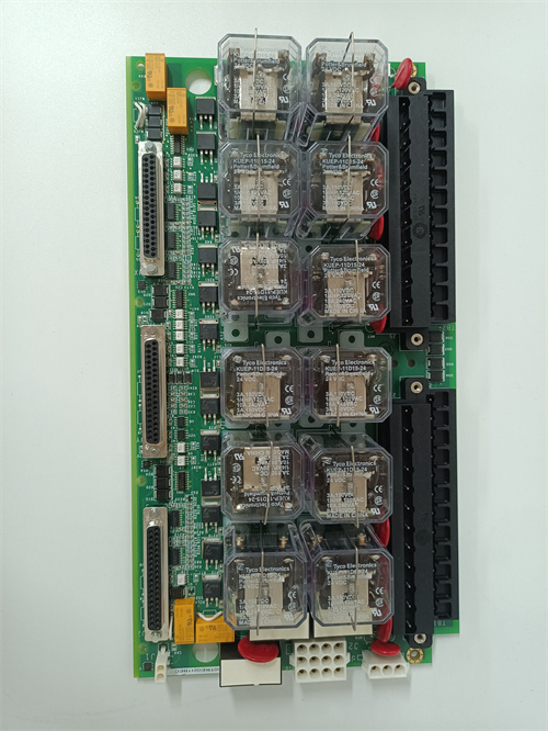
The GE IS200EDCFG1A Exciter DC Feedback Board (EDCF) is a critical component of the GE EX2100 Excitation Control System.1 Its fundamental role is to provide precise, isolated, high-speed feedback of the generator’s Field Current and Field Voltage to the main control system.2
This feedback is essential for the EX2100 system to perform closed-loop control of the SCR (Thyristor) bridge, thereby regulating the generator’s output voltage and reactive power.3
⚙️ Core Functions and Measurement
The EDCF board is situated near the SCR bridge in the exciter power cabinet and is designed to handle high-voltage and high-noise environments.4
1. Field Current Measurement
- Measurement: Field current is measured across a DC shunt located at the SCR bridge.5
- Signal Conditioning: The shunt generates a low-level signal (up to a maximum of 500 mV).6 This signal is then fed into a differential amplifier, which outputs a voltage ranging from 7$-5\text{ V}$ to 8$+5\text{ V}$ into a voltage-controlled oscillator (VCO).9
2. Field Voltage Measurement
- Measurement: Field voltage is measured across the negative terminal of the bridge and the positive terminal of the current shunt.10
- Scaling: The voltage feedback circuit provides seven selector settings (jumper-selectable) to scale down the high bridge voltage to a manageable level.11
- Signal Processing: The scaled voltage is then input into a differential amplifier, which controls another VCO.12
3. Isolated Communication (The Key Feature)
A crucial feature of the EDCF board is its interface with the main control panel:13
- Fiber-Optic Link: The conditioned current and voltage feedback signals are transmitted to the EISB (Exciter Interface Signal Board) in the control cabinet via high-speed fiber-optic links (two fibers are used: one for current, one for voltage).14
- Benefits: This fiber-optic link provides superior noise immunity and voltage isolation between the high-power bridge circuit and the sensitive control electronics, which is vital for system reliability and safety.15
🛠️ Technical Specifications
| Feature | Details |
| System | GE EX2100 Excitation Control System |
| Function | Measures Field DC Current and DC Voltage at the SCR Bridge |
| Communication | High-Speed Fiber-Optic Link (to EISB board) |
| Voltage Scaling | 7 Jumper-Selectable Settings for Field Voltage |
| Power Supply | Requires an external $\pm 24\text{ V DC}$ source (regulated to $\pm 15\text{ V DC}$ and $+5\text{ V DC}$ internally) |
| Diagnostics | Includes a PSOK (Power Supply OK) green LED indicator. |
The IS200EDCFG1A is thus the critical link that transforms high-power DC measurements into a highly accurate, noise-immune digital signal for the EX2100 controller.16