+86 15340683922
 +86 15340683922
الوصف
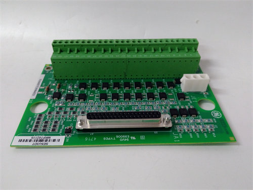
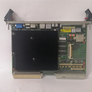
The GE IS200FCGEH1ADA LCI Control and Gating Board (FCGE) is a highly specialized circuit board used in Load Commutated Inverter (LCI) Drive Systems from General Electric, often integrated with the Mark VI turbine control platform.
Its primary function is to serve as the crucial interface and control module for the motor field exciter within the LCI drive system.
⚡ Core Functions of the FCGE Board
The FCGE board manages the precise control, monitoring, and synchronization of the excitation power for the synchronous motor/generator being driven by the LCI.
- Gating Command Relay: It receives gating (firing) commands from the LCI processor board (the main controller) and relays these signals to the power devices (Thyristors or SCRs) in the exciter bridge. This controlled firing is what regulates the voltage and current supplied to the motor’s field winding. It has six firing command output drivers, each corresponding to a cell string in the exciter bridge.
- Feedback Conditioning: It conditions and processes voltage and current feedback signals received from the exciter power bridge. This conditioned data is then sent back to the LCI processor board, allowing the controller to perform closed-loop regulation and ensure stable, efficient operation.
- Ground Fault Detection: It includes internal circuitry to detect ground faults originating from the DC exciter bridge. If a fault is detected, the FCGE triggers a protective signal to shut down the system.
- System Diagnostics: The board features an internal system clock for timing and a heartbeat function with LED indicators (IMOK and ACTIVE). These features provide quick diagnostic feedback on the board’s operational status and communication link with the main processor.
🛠️ Technical Context
- System: LCI (Load Commutated Inverter) Drive System, often tied to the GE Mark VI series.
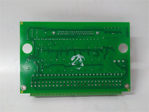
- Mounting: It is a VME-type board, designed to be mounted within the VMEbus rack inside the LCI control cabinet.
- Connectivity: It utilizes 96-pin VMEbus connectors (P1 for standard I/O and P2 for I/O interfacing with the host processor and exciter) to communicate with other boards in the system.
- Inputs: The board typically has six analog voltage inputs to monitor various parameters within the exciter bridge.
This board is essential for maintaining the synchronous motor’s flux and providing high-speed protection, ensuring the reliability of the entire LCI drive and the turbine’s operation.