+86 15340683922
 +86 15340683922
الوصف
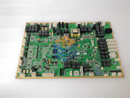
The GE IS200ISBDG1AAA is a printed circuit board for the Mark VI Speedtronic Turbine Control System and is known as the Insync Delay Board or ISBus Delay Module.
While some sources apply the name “Phase Carrier Control Power Detector Board” to this specific part number, the functional acronym ISBD (Innovation Series Bus Delay) is more descriptive of its primary role.
⚙️ Core Function: ISBus Delay
The IS200ISBDG1AAA’s main function is to introduce a precise, calculated delay into the high-speed, proprietary ISBus communication signals.
-
Synchronization (InSync): In Triple Modular Redundant (TMR) Mark VI systems (R, S, T modules), all three control modules must receive critical synchronization signals at the exact same moment to ensure the voting logic and failover mechanisms work correctly.
-
Path Compensation: Due to microscopic differences in physical cable lengths or backplane properties, signals can arrive at the processors at slightly different times. The ISBD board contains active circuitry to deliberately delay the signal transmission to one or more modules, compensating for these physical variances.
-
System Integrity: By adjusting the signal timing to achieve perfect synchronization, the ISBD module is essential for maintaining the real-time integrity of the TMR system, which is critical for the reliable and continuous operation of the turbine.
🔎 Alternative Function and Connectors
Although its primary function is the ISBus delay, the board is also equipped for serial communication and power detection, which may lead to the other descriptive name you provided:
-
Phase Carrier Control Power Detector: This suggests the board may also be involved in monitoring power phases or control signals, particularly in excitation or drive systems.
-
Serial Communication: The board is also described as a serial communication board providing up to six serial communication ports (supporting RS-232C, RS-485, and RS-422 interfaces) for connecting to external devices like sensors and actuators.
-
Connectors: The board features:
-
P4 terminal strip (often labeled 24 VDC Input).
-
A vertical male ribbon connector (P5) and other connectors labeled Full Duplex, XMIT Out, and RCV In.
-
LEDs (labeled “Fail,” “Run,” and “Status”) for diagnostics.
-
The G1AAA suffix indicates that this is the first hardware group (G1) with a specific triple-A assembly revision of the board.
| SC510 |
| SNAT603CNT |
| SPAD346C3 |
| UAD149A0011 |
| UFC719AE01 |
| UFC760BE42 |
| UNITROL-1010 |
| UNITROL-1010 |
| XVC517AE10 |
| YPK112A |
| 320-1026C |
| TECH-12000-310 |
| TECH-20000-310 |
| 022365-A000824B |
| CM01-CM01-A-V001 |
| DI3201-DI3201-A-V001 |
| DO3201-DO3201-A-V001 |
| DSAI130-57120001-P5 |
| A4H254-8F8T |
| ETT-VGA-0045 |
| 369B1860G0028 |
| 8521-LC-MT |
| 8851-LC-MT |
| 0880001-01 |
| AT686W |